Lock Pin (Detail G + H)

Grease
Hammer
T handle Screwdriver
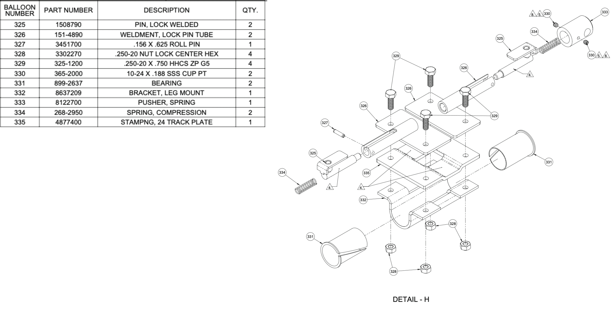
1508790 (Lock welded pin).
151-4890 (Lock pin tube weldment)
268-2950 (Compression spring)
fixture 933-0105
3451700 (.156 x .625 Roll pin)
Apply grease to the entire cylindrical section of the 1508790 (Lock welded pin).

Slide the lock welded pin into the 151-4890 (Lock pin tube weldment)
a. The lock welded pin should slide into the u-shaped cutout in the lock pin tube weldment.
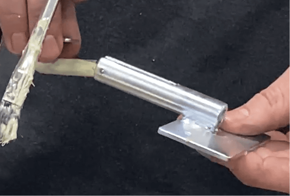
Insert 268-2950 (Compression spring) into the cylindrical opening in the lock welded pin/lock pin tube weldment. Make sure it is as far into the tube as it can go.

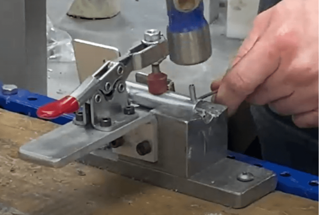
Place the subassembly into fixture 933-0105. Place it in a sideways orientation, with the tube on the operator side and pointing to the left (operator’s POV left, seen pointing right below); the flat end is slid beside the fixture. Secure the tube section by pressing the red knob lever down towards the table.

Hammer in 3451700 (.156 x .625 Roll pin) into the upward facing hole. (Picture: can use a T-handle screwdriver to help secure the roll pin while hammering).