
Detail N (Load End Brace)

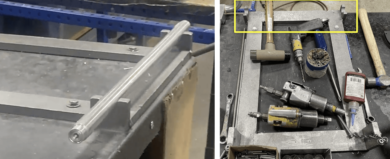
Sander
Pop rivet Gun
Marking Pin
Hammer
Power Drill
.152 Bit
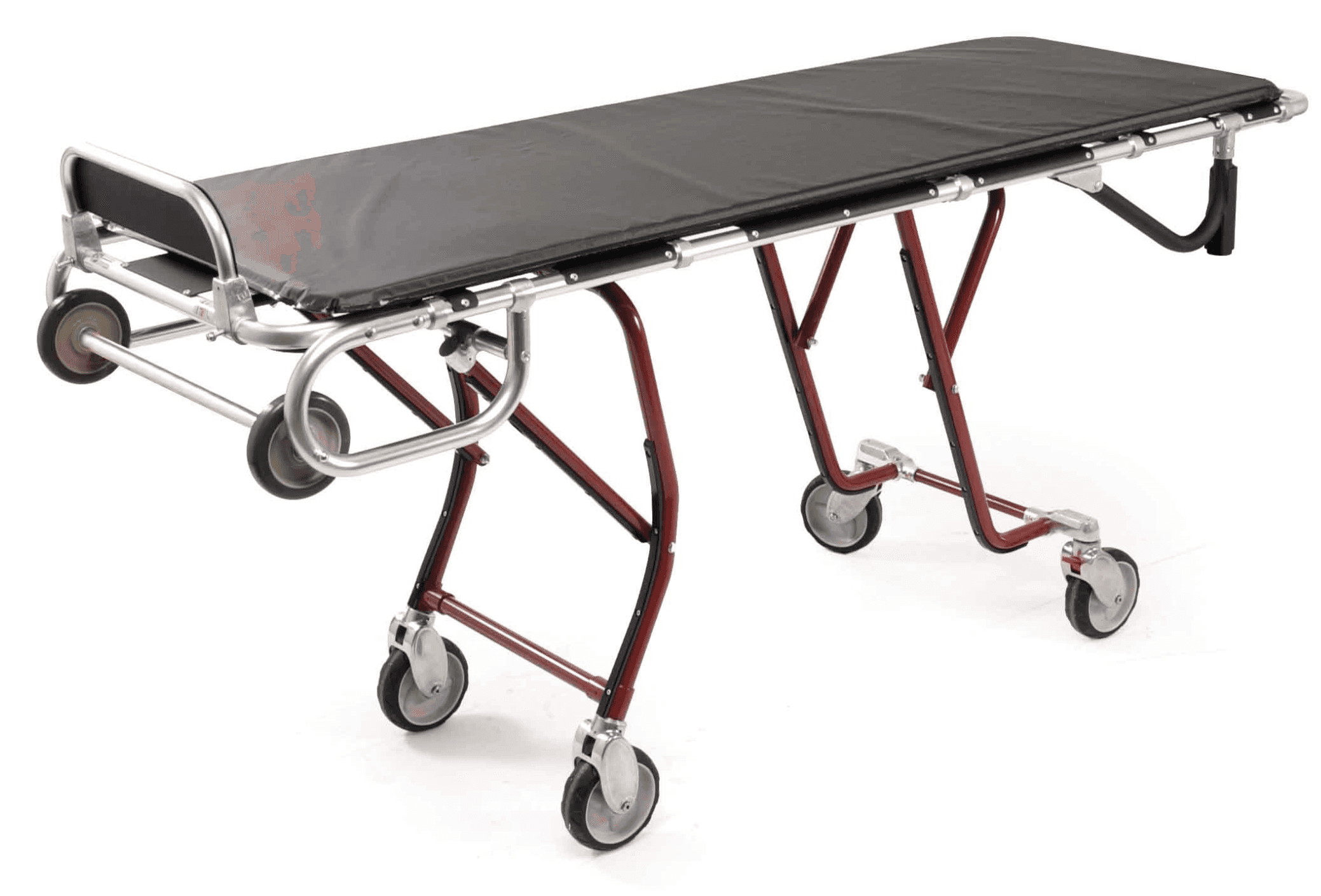
1525990 (Load end crosstube, miniMAXX)
fixture 1513880.
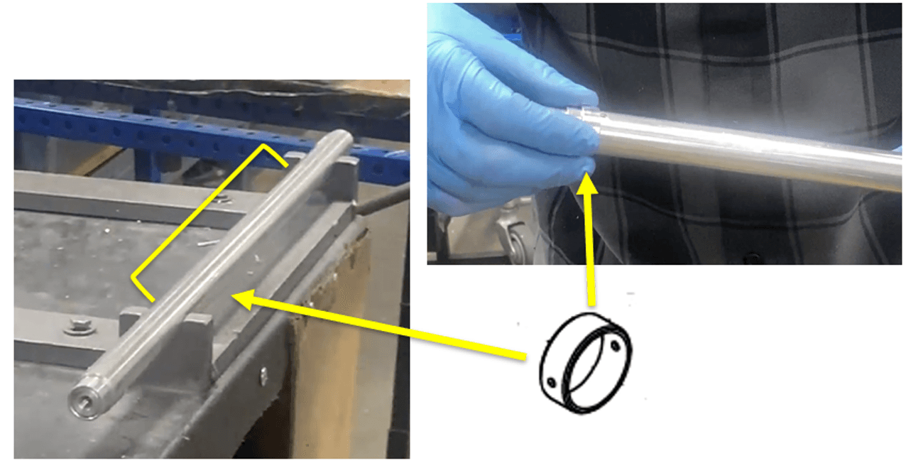
819-6980 (Ring spacer)
506-1601 (61-5TT Offset tee)
8192086 (Load end leg brace)
scuff strip (8480260)
340-2200 (Pop rivet AD-66-H)
8480260 (Scuff strip)
8192086 (Load end leg brace)
340-2200 (Pop rivet AD-66-H)
345-2600 (.156 X 1.250 Roll pin)

Place the 1525990 (Load end crosstube, miniMAXX) onto fixture 1513880.
Slide an 819-6980 (Ring spacer) onto one side of the tube. Let it sit past the pre-drilled pin hole. This could be anywhere between the fixture contact points.
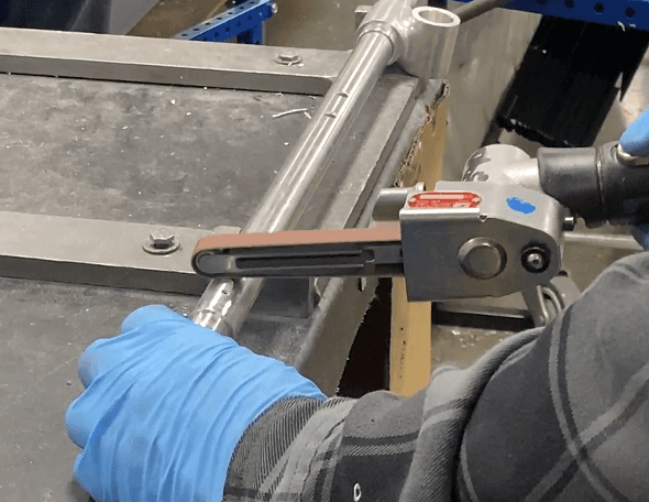
Optional: If the ring spacer does not slide on easily, sand down the pre-drilled pin holes at the crosstube ends.
b. Note: The pre-drilled pin holes are thru holes; if sanding is needed, check both openings.
On the same side the ring spacer was slid onto, slide a 506-1601 (61-5TT Offset tee) onto the crosstube. Let it rest on the inside face of the fixture contact point. Slide the ring spacer against it.
Optional: If the offset tee does not slide on easily, sand down the pre-drilled pin hole at the crosstube ends

Do steps 2 and 3 for the other side of the crosstube: slide a ring spacer and an offset tee onto the other end of the crosstube.
Optional: Sand the crosstube ends (the pre-drilled pin holes) where necessary.

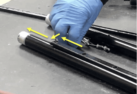
Insert the silver end of 8192086 (Load end leg brace) -- the scuff strip (8480260) already secured to it – into the offset tee’s hole. Do this for each offset tee. They should be able to be pushed in by force with a resulting snap sound.
If the load end leg brace + scuff strip has not been assembled, follow steps 6-9.
If it has been assembled, go to step 10.
Optional: Sand the silver ends if necessary.

Place an 8480260 (Scuff strip) onto an 8192086 (Load end leg brace). The orientation should be that the slope of the ends of the strip forms an obtuse angle with the tube (like a slide, no gap). The chamfered/pointed end should face the leg.
Align the four holes of the scuff strip with the holes on the leg.
Place 340-2200 (Pop rivet AD-66-H) into the four holes of the scuff strip and the leg. Use a pop rivet gun to secure the rivets into the holes.


Repeat steps 6 through 8 to create a second load end leg brace + scuff strip subassembly.
Insert a tooling pole into both leg brace’s ends: this helps keep the offset tees and leg braces in place for the next step.

Using a pin and hammer, place a mark on the section of the offset tee with the leg brace inserted, approximately 0.5-1 cm away from the edge/opening edge. The marks should face each other, towards the center.
a. For the left offset tee, the mark should be on its right side.
b. For the right offset tee, the mark should be on its left side.

Use a .152 drill bit to drill a hole through these two marks. Drill completely through the tees in the direction parallel to the cross tube.
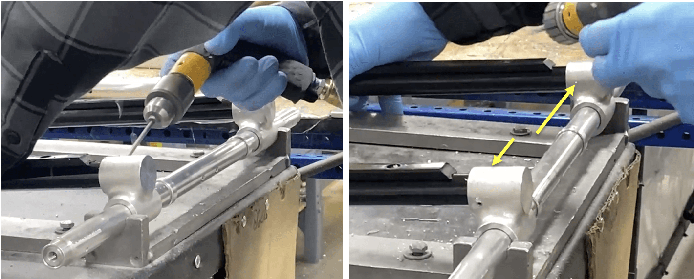
Hammer in 345-2600 (.156 X 1.250 Roll pin) into the two holes. They should end up nearly flush with the offset tees.
a. Optional: if they are not flush and stick out, sand down the ends of the roll pins until they are flush with the offset tees.

Remove the tooling pole from the leg braces and remove the sub-assembly from the fixture. Place in WIP storage.