
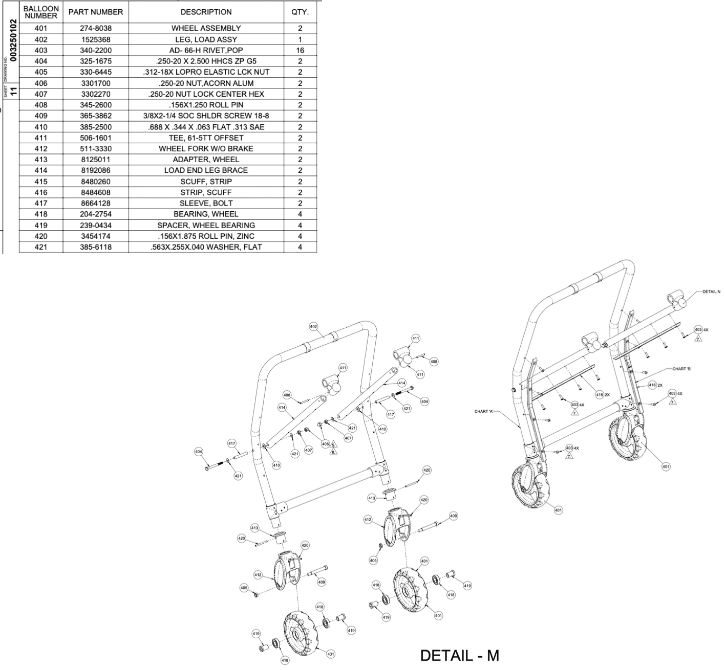
Detail M (Load End Leg Frame)

Ratchet Wrench
Power Drill
.152 Bit
Hammer
Roll Pin Starter
Pop Rivet Gun
Mallet
T-handle wrench
Attach plastic bearings onto the middle part of part number 1525368 (Leg, Load Assy).
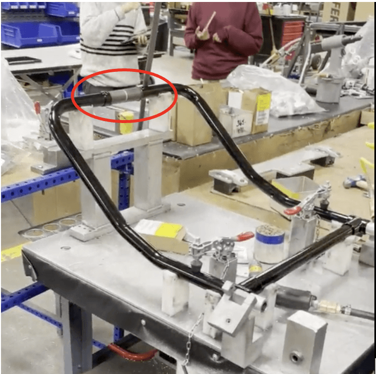
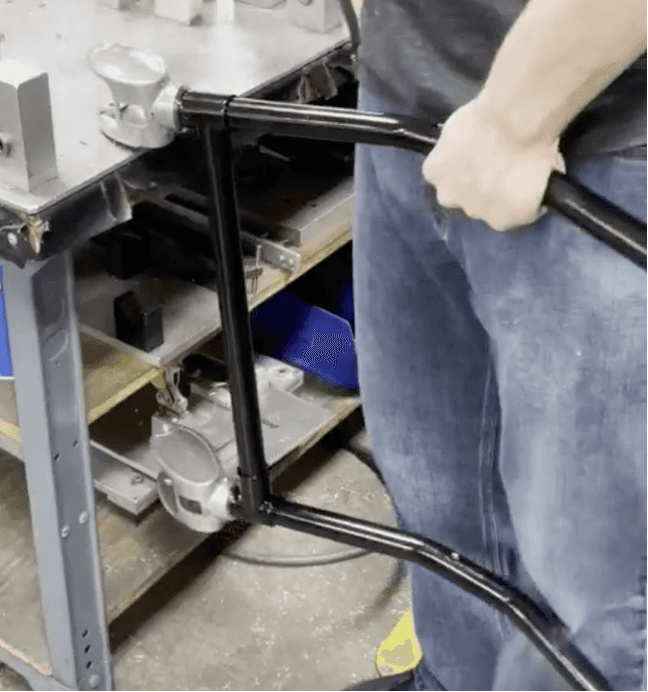
Take part number 1525368 (Leg, Load Assy) and attach part number 511-3330 (Wheel Fork W/O Brake) to one of the bottom sides.
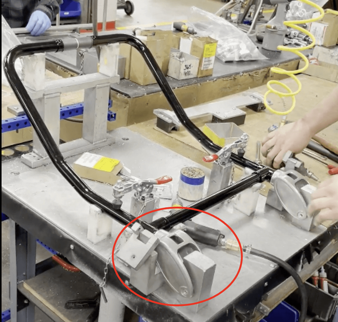
Take part number 365-3862 (3/8X2-¼ Soc Shldr Screw 18-8) and use a ratchet wrench to secure the part into the holes at the bottom of part number 511-3330 (Wheel Fork W/O Brake).

Repeat steps 2-3 for the other side
Lock the fixture covers onto both sides
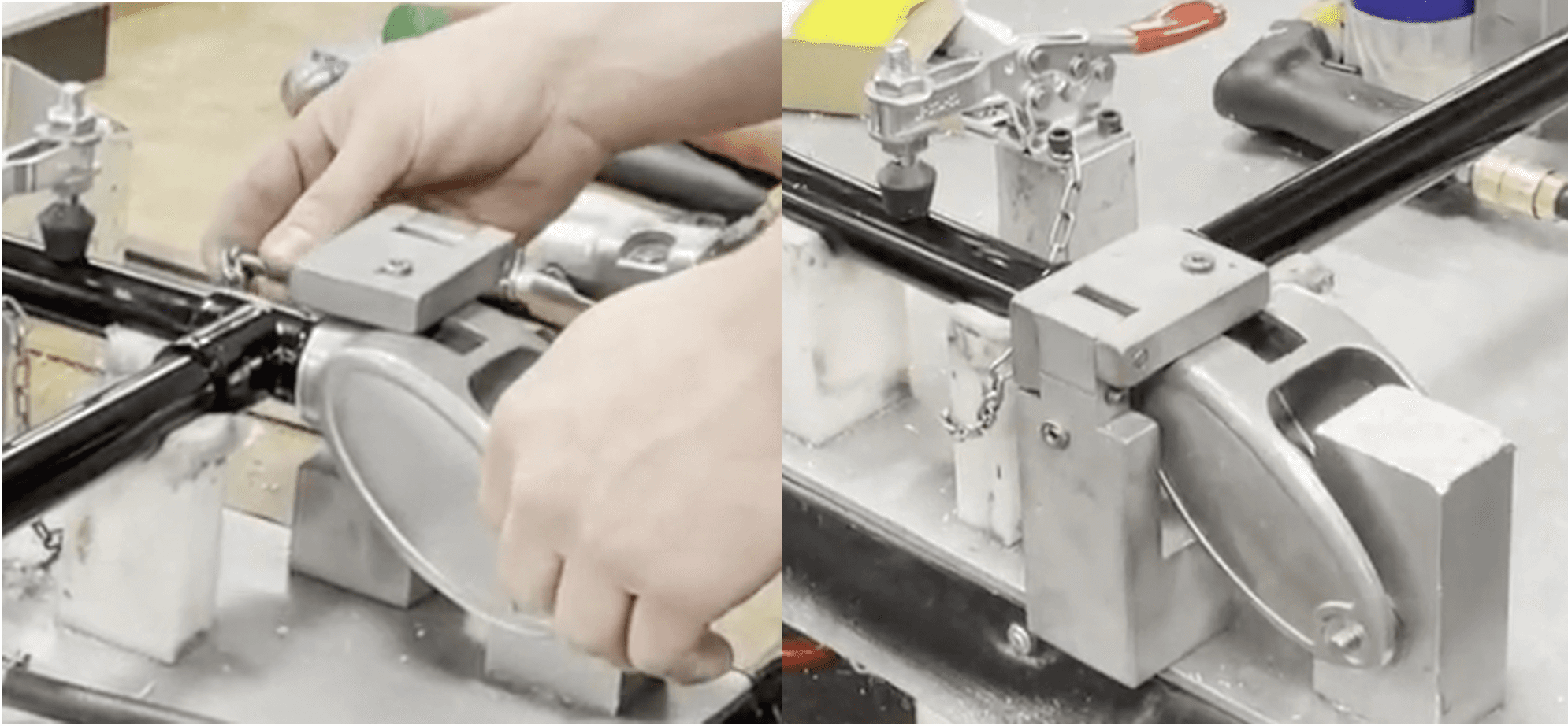
Using a .152 drill bit, drill a hole through the existing hole on the top of 24-MiniMAXX fixture
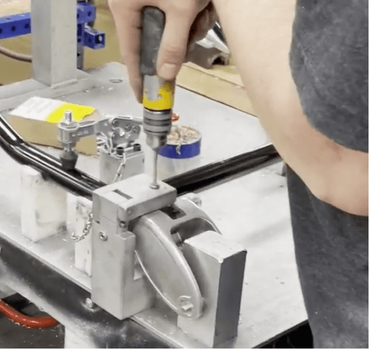
Using the same drill bit size, drill a hole through the existing hole on the side of the 24-MiniMAXX fixture

Repeat steps 6-7 on the other side
Unlock the fixture covers on both sides and flip them to the side

Using the same drill bit size, finish drilling a hole all the way through the already marked hole on the top of both sides
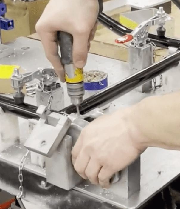
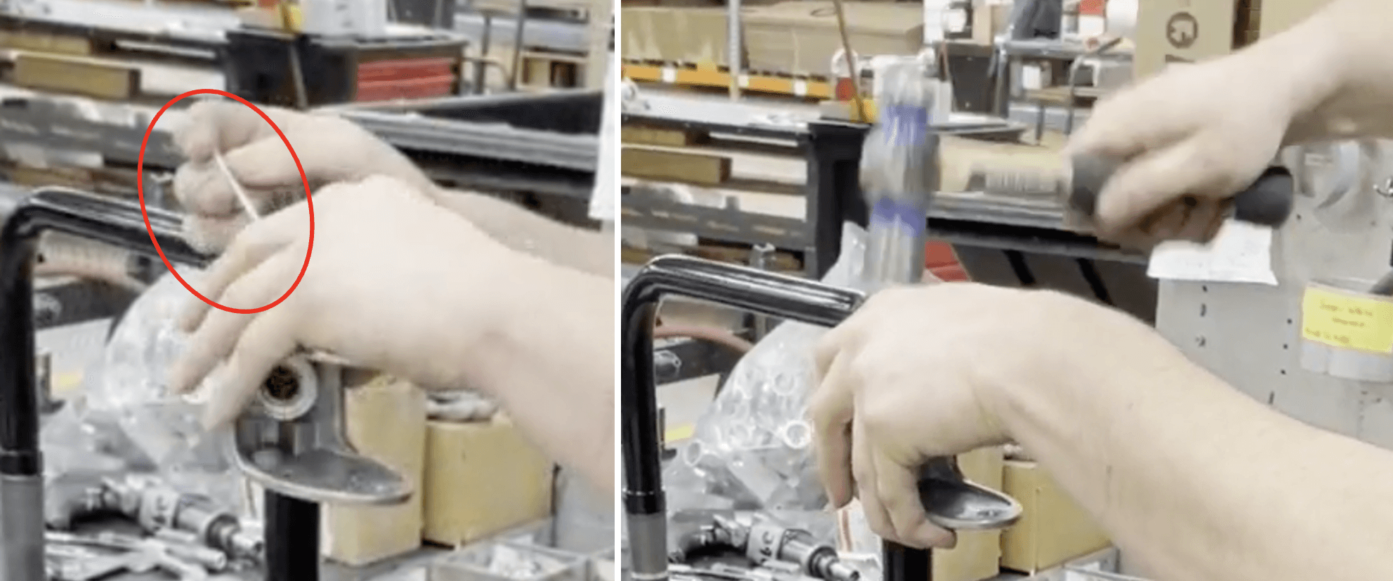
Take 2 of part number 3454174 (.156X1.875 Roll Pin, Zinc) and hammer them into the drilled holes on the top of both sides
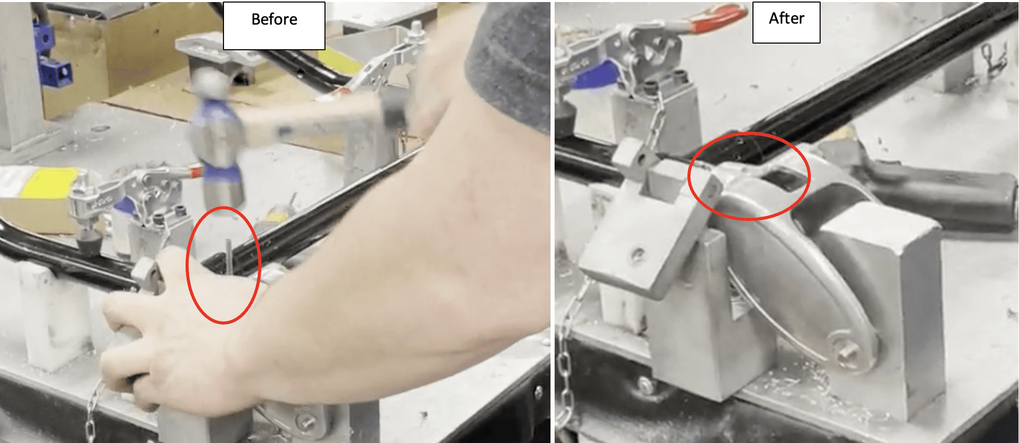
Use a roll pin starter and line it up with where one roll pin was just hammered in
Hammer the top of roll pin starter a few times

Repeat steps 12-13 for the other side
Unlatch red handles on the fixture

Remove part number 365-3862 ((3/8X2-¼ Soc Shldr Screw 18-8) from part number 511-3330 (Wheel Fork W/O Brake) on both sides using a ratchet wrench.

Remove the assembled part from the fixture and rest part number 511-3330 (Wheel Fork W/O Brake) on one side on the counter.
Using a .152 drill bit, drill a hole all the way through into the side of the top of part number 511-3330 (Wheel Fork W/O Brake) where there is already a hole.

Flip the assembled part around so that the other side’s part number 511-3330 (Wheel Fork W/O Brake) is resting on the counter.
Repeat step number 18
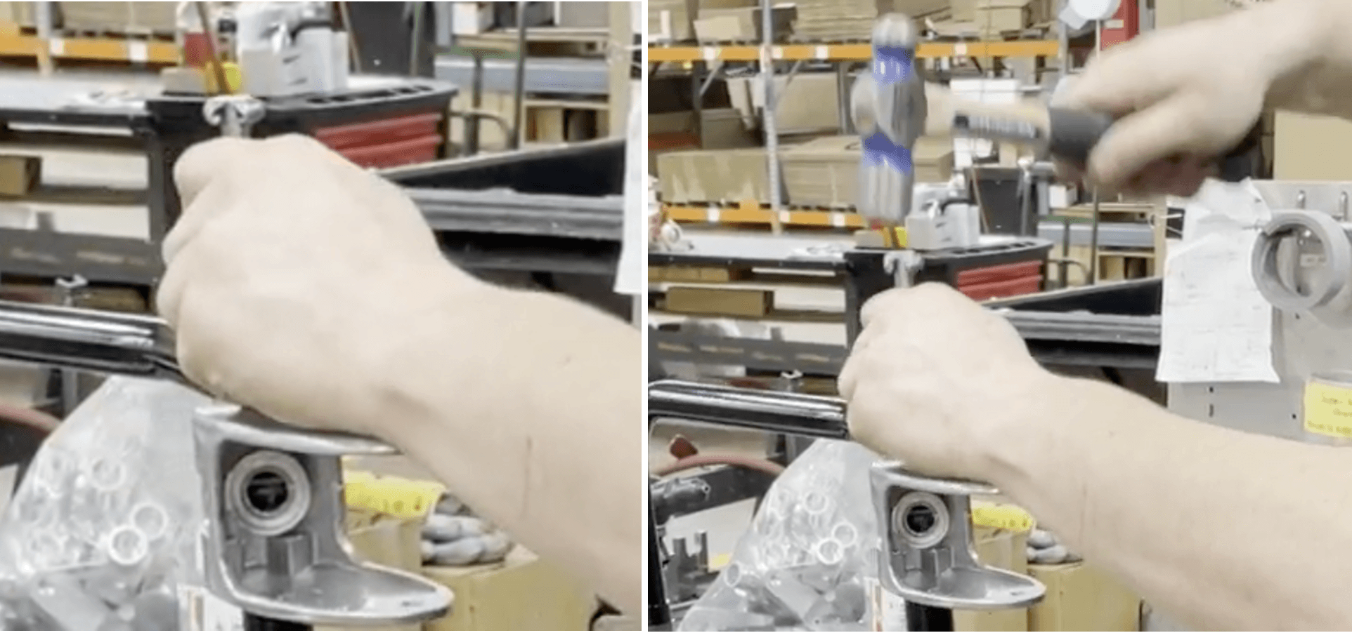
Hammer part number 3454174 (.156X1.875 Roll Pin, Zinc) into the hole that was just drilled on the side of part number 511-3330 (Wheel Fork W/O Brake)
Use the roll pin starter and line it up with where the roll pin was just hammered in
Hammer the top of the roll pin starter a few times
Repeat steps 21-23 for the other side
Lay assembled part down flat and place 24-MiniMAXX fixture onto it

Using a .152 drill bit and one of the template holes on the 24-MiniMAXX fixture, drill through one wall on part number 1525368 (Leg, Load Assy) in designated spot.
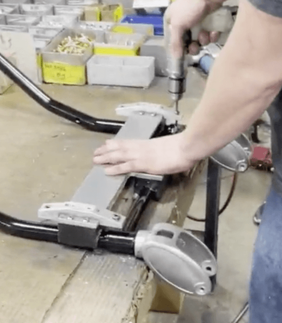
Repeat step 26 for the other three template holes on the 24-MiniMAXX fixture

Remove 24-MiniMAXX fixture

Wipe down the area that was just drilled through to remove any shards

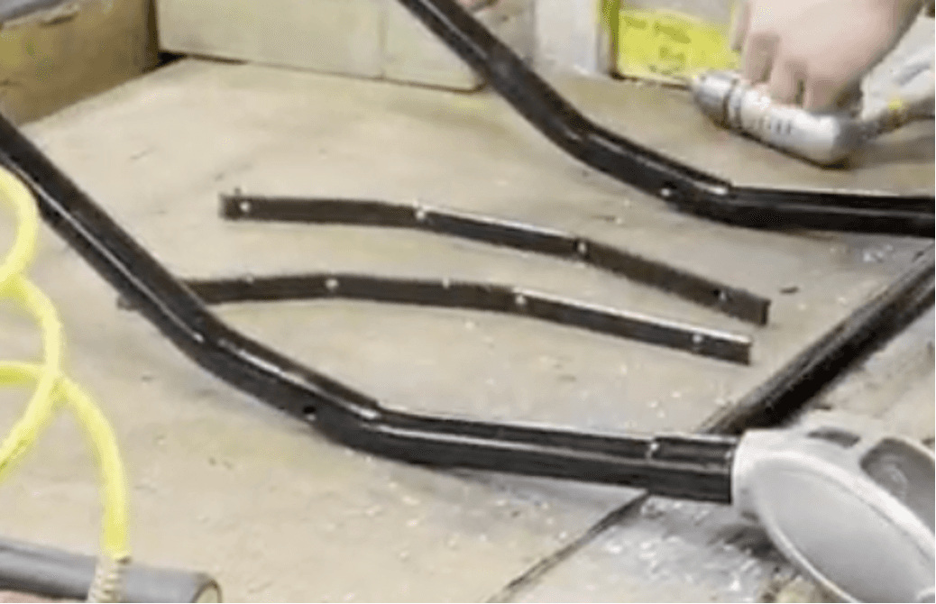
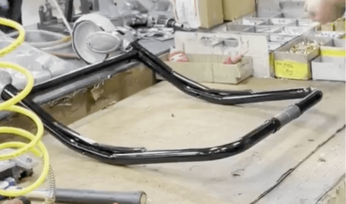
Grab two of part number 8484608 (Strip, Scuff) and bend them to look like the picture below
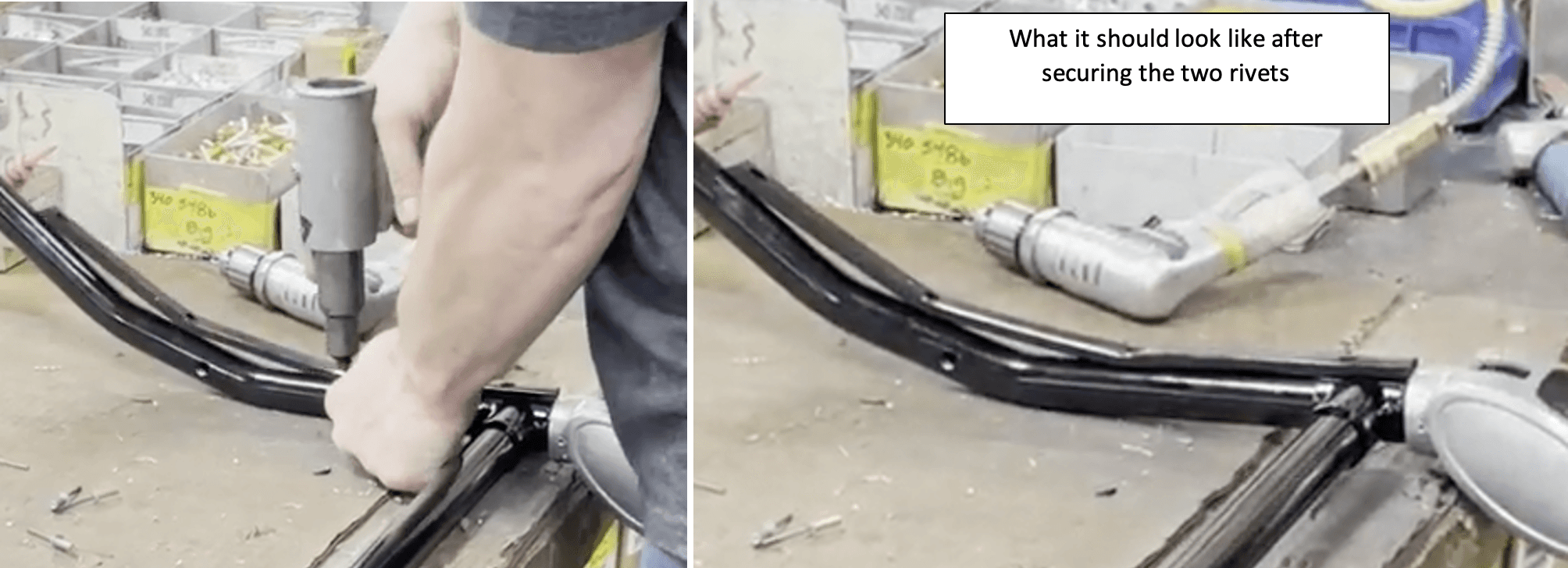
Take one of the part numbers 8484608 (Strip, Scuff) and align its two bottom holes with the two holes at the bottom of one of the sides of part number 1525368 (Leg, Load Assy)
Take two of part number 240-2200 (AD- 66-H Rivet, Pop) and place them into the aligning holes

Use a pop rivet gun to secure the two pop rivets
Repeat steps 31-33 for the other side of part number 1525368 (Leg, Load Assy)
Using a .152 drill bit, drill through one wall of 1525368 (Leg, Load Assy) where it aligns with one of the top four holes of part numbers 8484608 (Strip, Scuff)
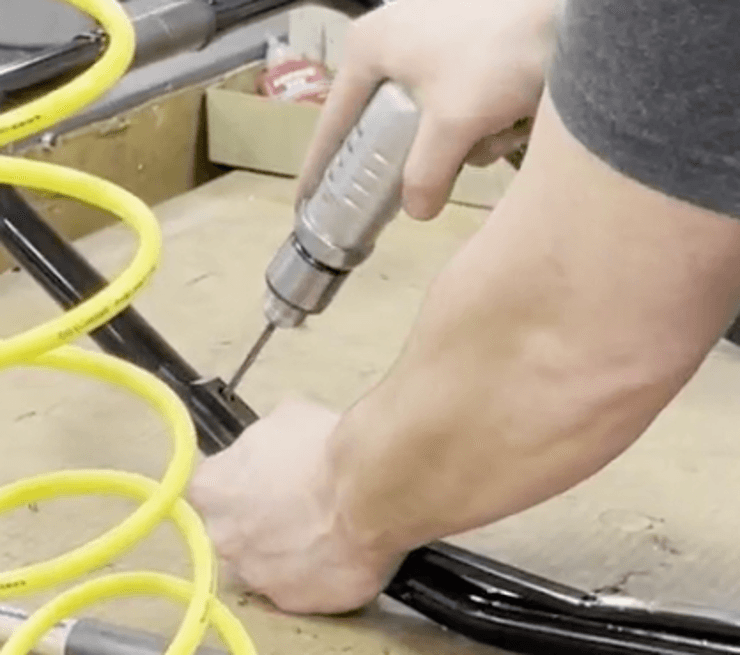
Repeat step 35 for the other three top holes on both of part number 8484608 (Strip, Scuff)
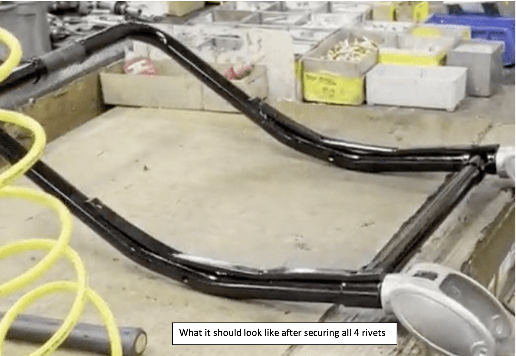
Grab four more of part number 240-2200 (AD- 66-H Rivet, Pop) and place them into the 4 holes that were just drilled
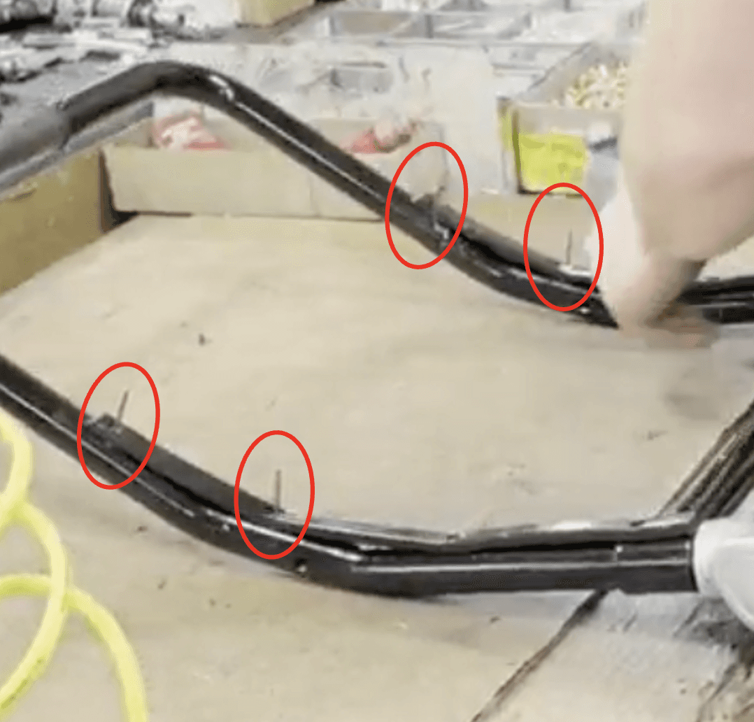
Use a pop rivet gun to secure all four of the pop rivets

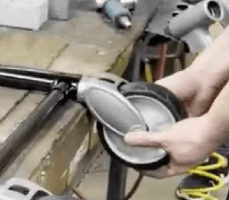
Grab two of part number 274-8038 (Wheel Assembly)
Take two of part number 204-2754 (Bearing, Wheel) and place one into the center of each part number 274-8038 (Wheel Assembly)
Hit each one into place with a mallet

Flip over both Wheel Assemblies and repeat steps 40-41
Take two of part number 239-0434 (Spacer, Wheel Bearing) and place each one into the center of part number 204-2754 (Bearing, Wheel) on both Wheel Assemblies

Flip the wheels over a repeat step 43 for the other side
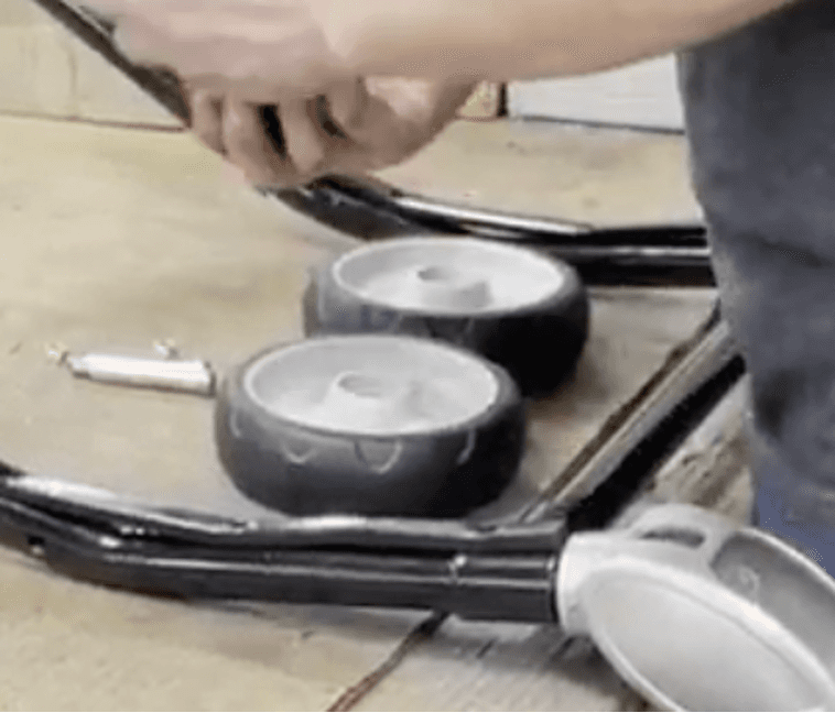
Take one Wheel Assembly and place it into part number 511-3330 (Wheel Fork W/O Brake) on the right side
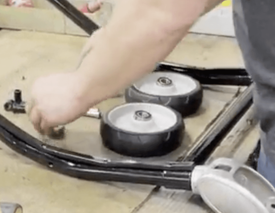
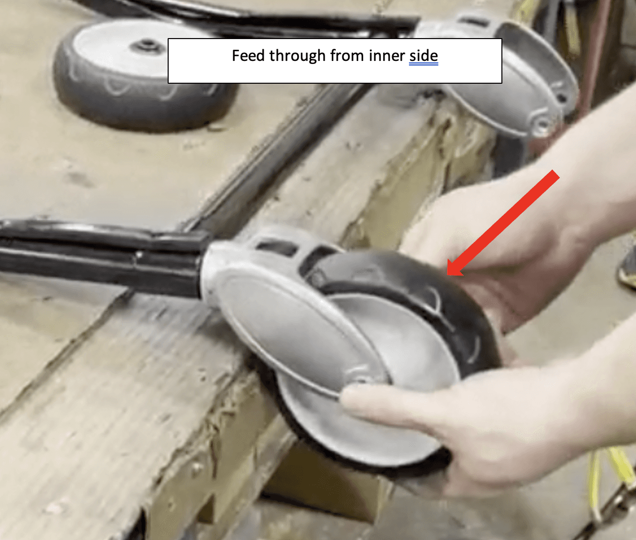
Take part number 365-3862 (3/8X2-¼ Soc Shldr Screw 18-8) and feed it through the holes on the bottom of part number 511-3330 (Wheel Fork W/O Brake) and the center hole of the Wheel Assembly on the right side from the outside


Repeat step 45-46 for the left side but ensure that part number 365-3862 (3/8X2-¼ Soc Shldr Screw 18-8) is being fed through from the inside
Use a ratchet wrench to tighten both part numbers 365-3862 (3/8X2-¼ Soc Shldr Screw 18-8)
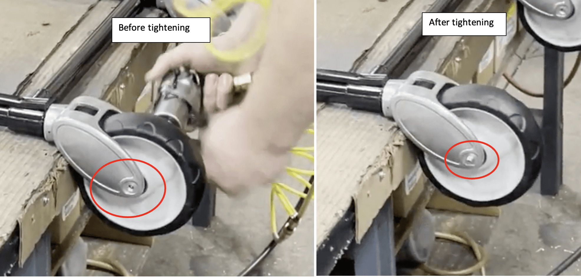
Take two of part number 330-6445 (.312-18X Lopro Elastic Lck Nut) and twist them onto the other ends of both part numbers 365-3862 (3/8X2-¼ Soc Shldr Screw 18-8)

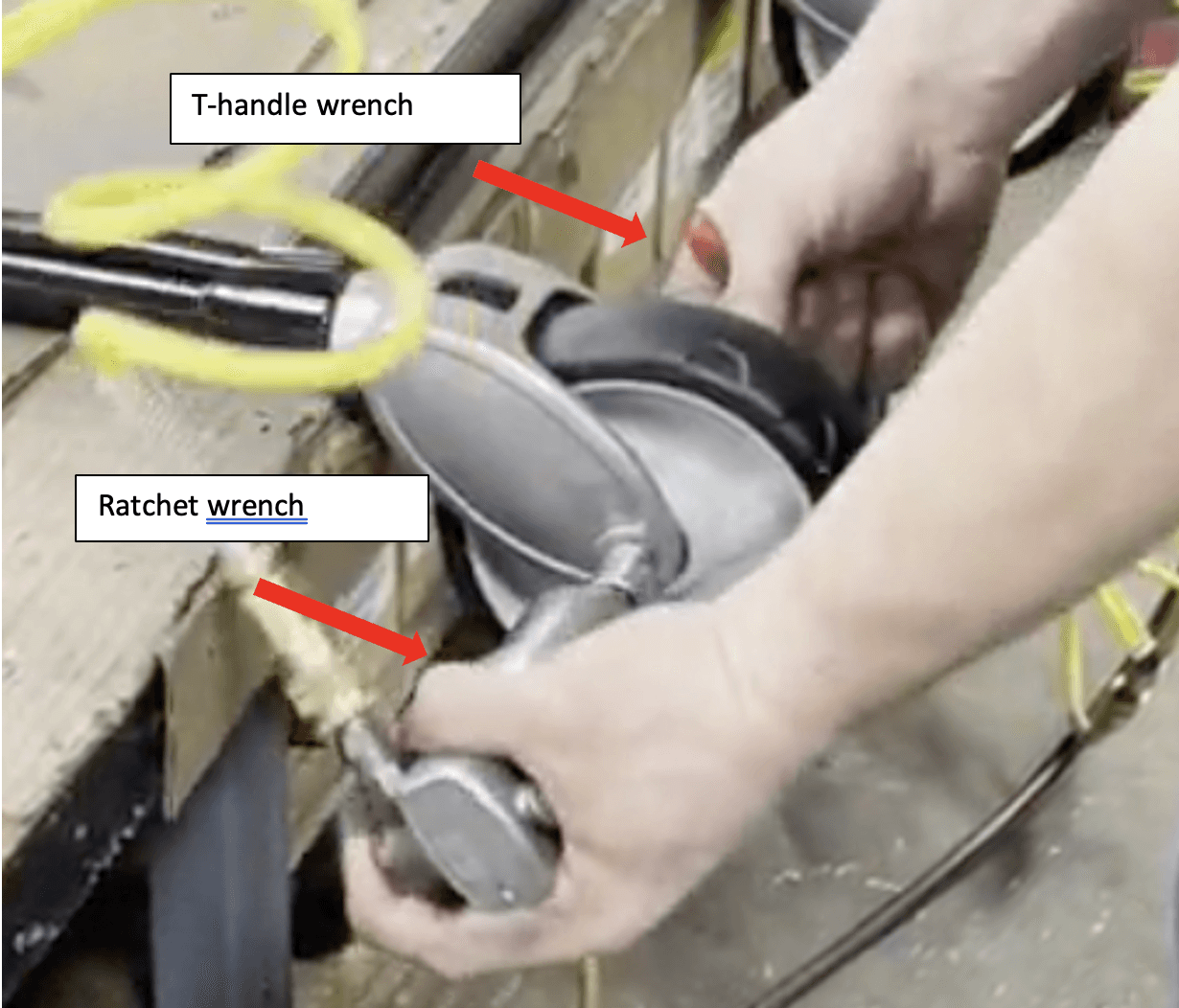
Using a T-handle wrench and ratchet wrench to tighten the part numbers 330-6445 (.312-18X Lopro Elastic Lck Nut) onto the part numbers 365-3862 (3/8X2-¼ Soc Shldr Screw 18-8)
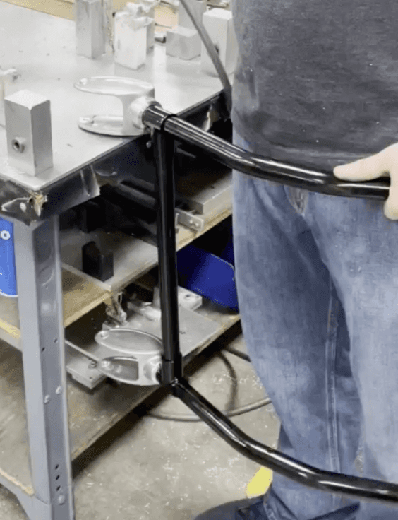
Tape both Wheel Assemblies

Flip assembled part around so that the top of it is facing you
Continue to Detail – H (Load End Brace) (See separate instruction)