Detail L (Operator End Leg Frame)


8481850 (Operator leg scuff strip)
1525363 (Operator end leg)
340-2200 (Pop rivet AD-66-H)
8664108 (.750X .065X 11.875 Stiffener)
8192084 (Foot cross tube)
5065489 (Left corner mount)
5065488 (Right corner mount)
385-6118 (.563X .255X .040 Flat washer)
8663935 (Bolt sleeve)
3251685 (0.2500-20x2.750 Hex head cap screws (HHCS ZP G5)).
385-2500 (.688 X .344 X .063 Flat .313 SAE flat washer)
3301700 (.250-20 center hex Lock nut)
385-2500 (.688 X .344 X .063 Flat .313 SAE flat washer)
blue 242 Loctite
3301700 (.250-20 Acorn alum nut)
3405486 (.250 MBCP-R8-M9 huck rivet)
340-5501 (.250 MBCP-R8-M7 huck rivet)
Loctite primer 7649 (690-4579)
red 262 Loctite
3204625 (.250-20X .750 Flat head machine screws (FHMS SKT 4140)).
152-5003 Wheel assembly (“Caster, With Brake”)
Operator End Leg Frame Piece
Note: These instructions are for assembling the subassembly that consists of the operator leg scuff strip (8481850) and the operator end leg (1525363). Scroll Down for full leg frame instructions.
Place 8481850 (Operator leg scuff strip) onto the 1525363 (Operator end leg). The orientation should be that the slope of the ends of the strip forms an obtuse angle with the tube (like a slide, no gap). The chamfered/pointed end should face the leg.
Align the holes of the scuff strip with the holes on the leg.
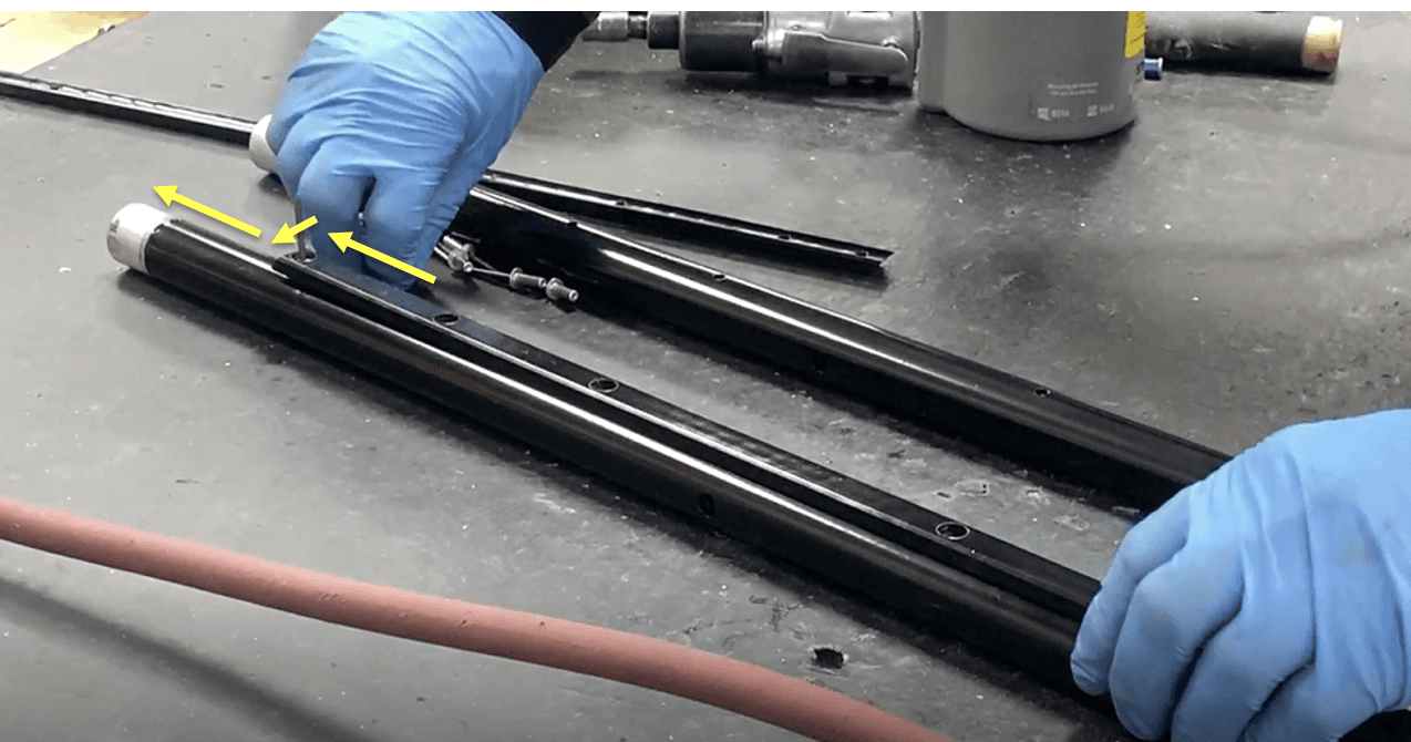
You will notice 2 holes of the strip scuff dangling off the apex of the leg at the bend.
i. 8 total holes, 6 flush with leg, 2 dangle.
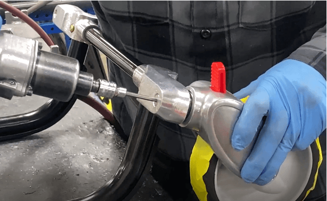
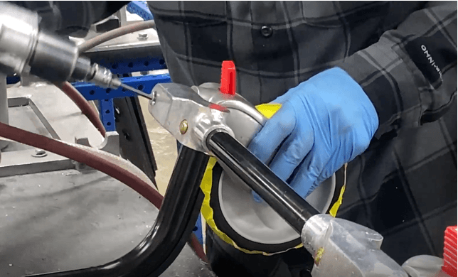
Place 340-2200 (Pop rivet AD-66-H) into these first 6 holes of the scuff strip and the leg. Use a pop rivet gun to secure the rivets into the holes.
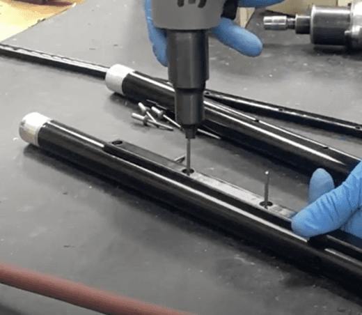
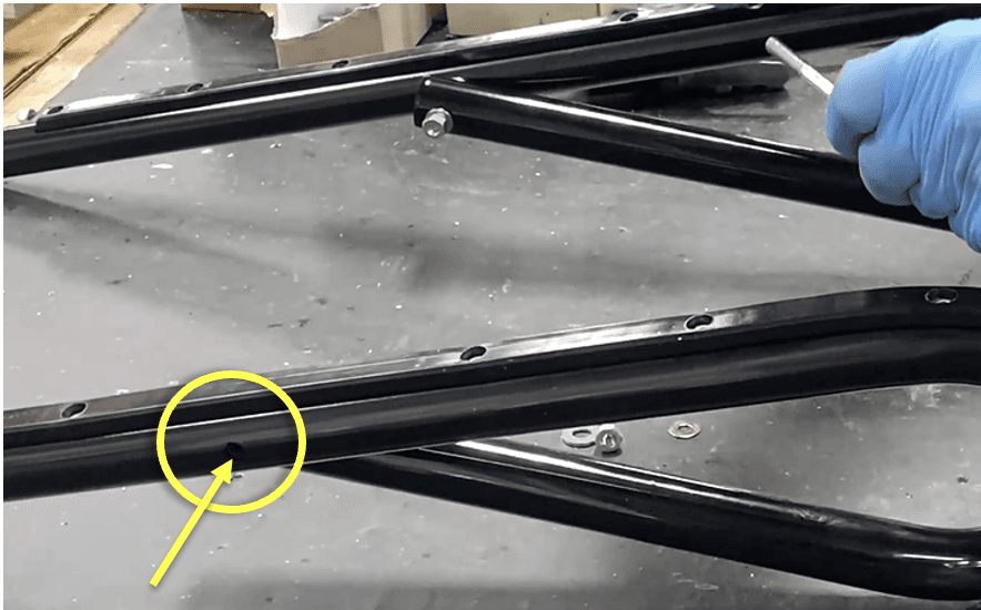
Bend the remaining scuff strip so it is flush with the leg. Notice there exists 2 holes in the scuff strip but not the leg.
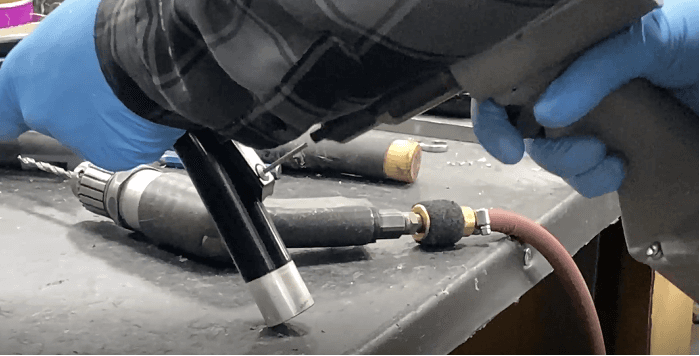
Drill a 3/16” hole through the hole closest to the curve and into the leg (like a stencil). Drill only through one wall of the operator end leg.
Place 340-2200 pop rivets into the hole of the scuff strip and the leg. Use a pop rivet gun to secure the rivets into the holes.
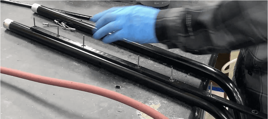
Repeat steps 5 and 6 with the last hole at the end of the scuff strip.
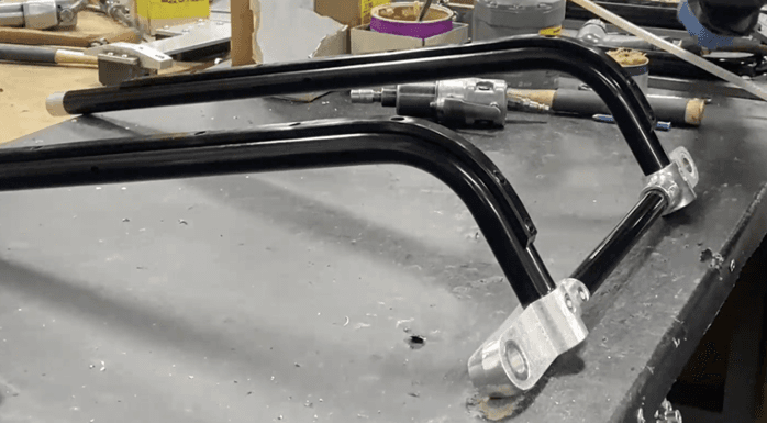
Repeat steps 1 through 7 to create a second operator end leg frame piece.
_______________________________________________________________________________________________________________
If not done already, insert 8664108 (.750X .065X 11.875 Stiffener) into 8192084 (Foot cross tube).
a. Otherwise, the foot cross tube should already have a stiffener installed.
Place corner mounts onto each side of the foot cross tube, curved end pointing out. Face the openings/holes up (as seen below).
Place 5065489 (Left corner mount) on the left opening
ii. Place 5065488 (Right corner mount) on the right opening.
b. Place the corner mounts on the cross tube ends as far as they can go. A hammer/mallet would help.
c. Orient it so that the corner mounts are mirroring/symmetrical to each other

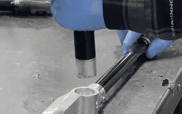
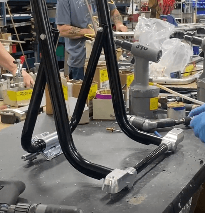
Insert an operator end leg frame subassembly piece (check “Operator End Leg Frame Piece Subassembly” Work instructions) into each corner mount opening. Insert as far as it can go.
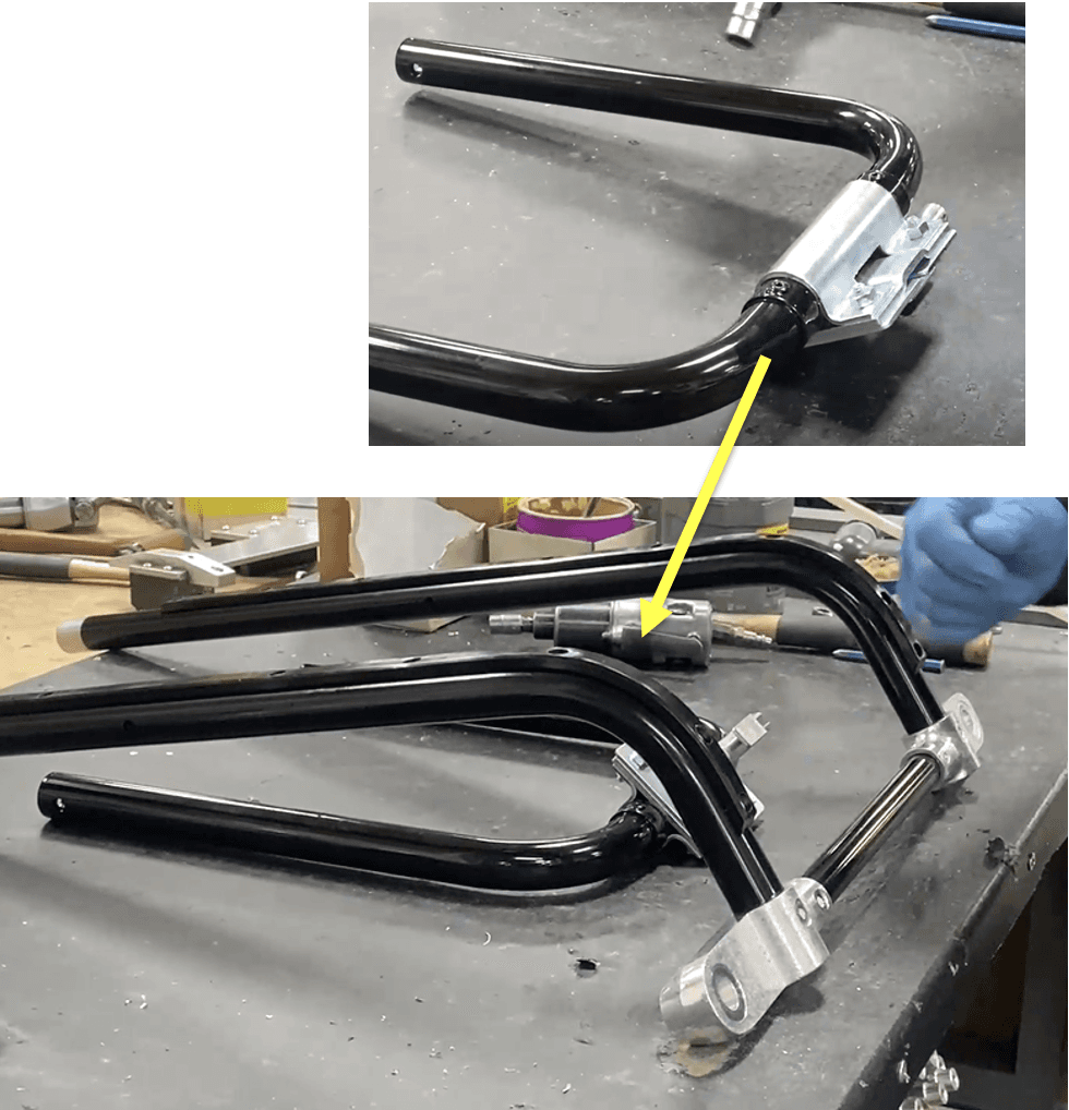
Place the operator end leg brace subassembly (check “Operator End Leg Brace Subassembly” Work instructions) by the current build as seen below. It will be attached to the current build in the next steps.
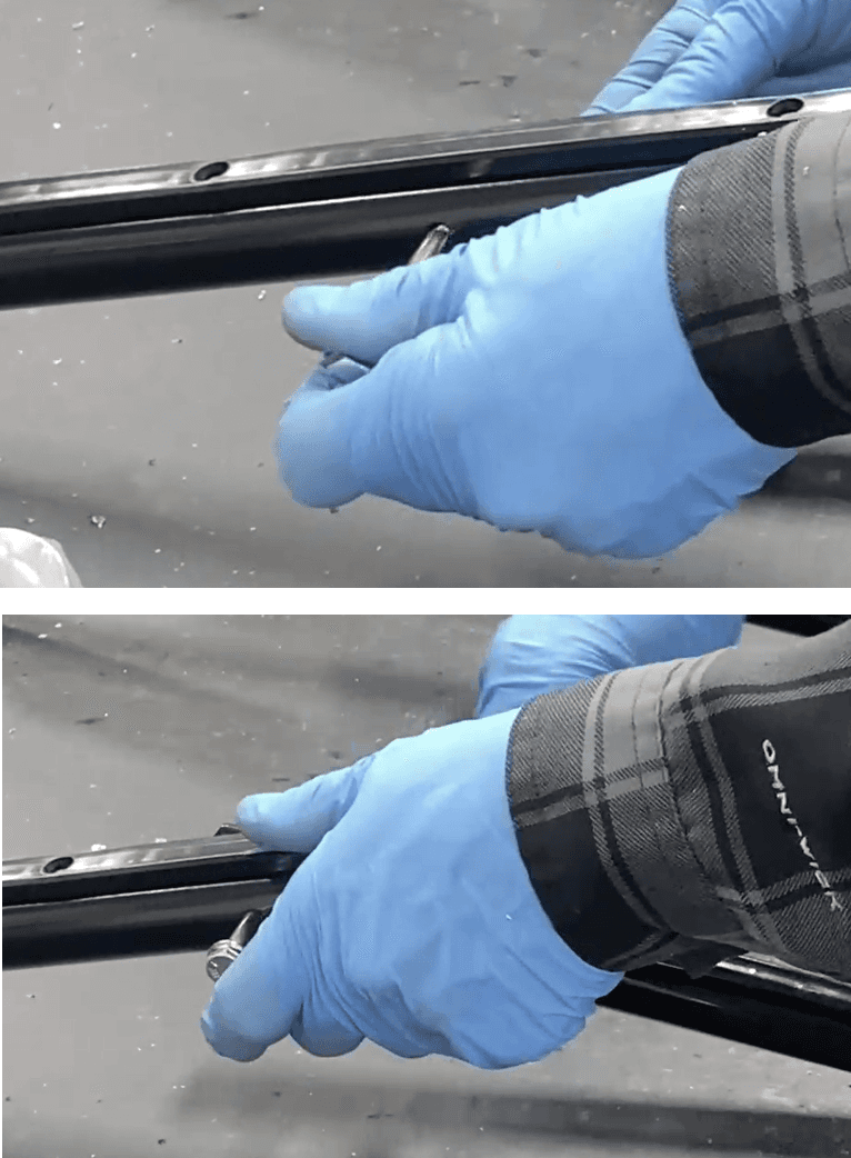
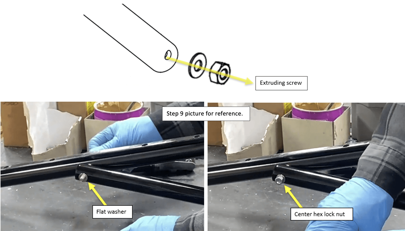
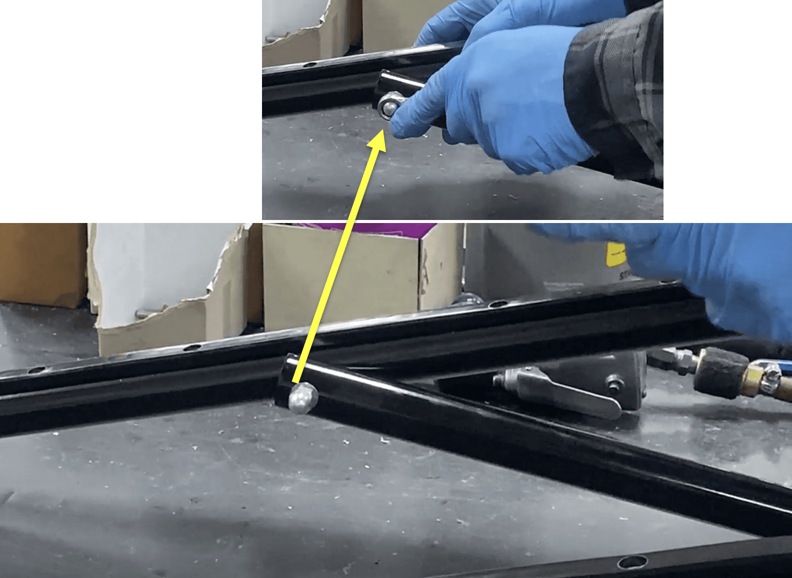
5. Place 385-6118 (.563X .255X .040 Flat washer) and 8663935 (Bolt sleeve) on a 3251685 (0.2500-20x2.750 Hex head cap screws (HHCS ZP G5)).
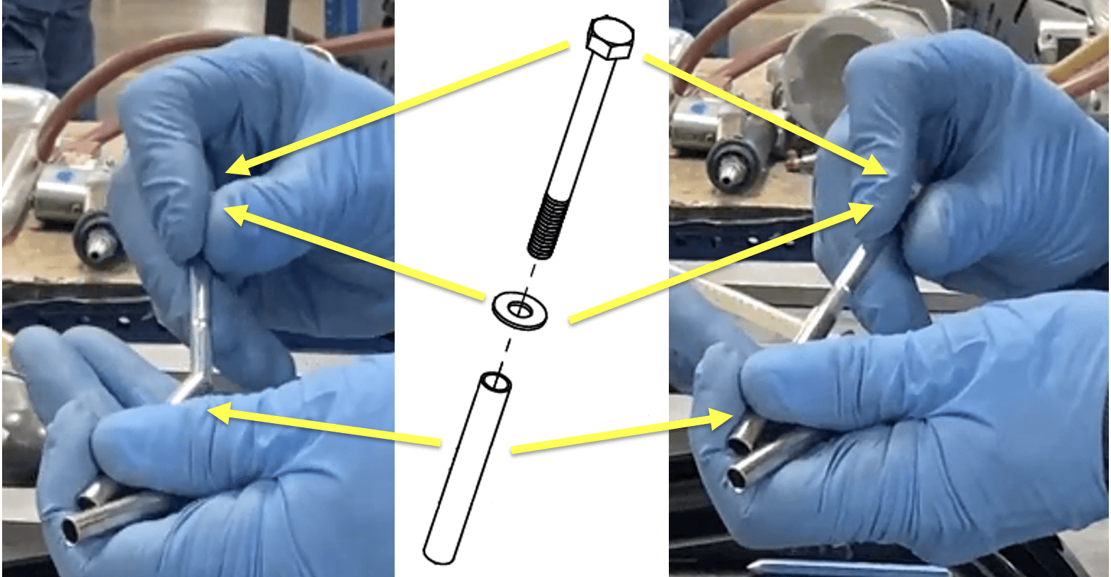
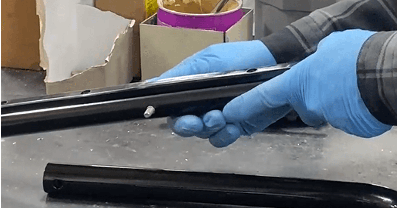
Insert the washer/sleeve/screw combination into the opening on the operator end leg, the end sticking out and pointing towards the center (the head of the screw should be on the outside of the frame). Push it all the way through the hole.
Place a 385-2500 (.688 X .344 X .063 Flat .313 SAE flat washer) onto the extruding screw.

Following the SAE flat washer, place one end of the operator end leg brace on the extruding screw (via the through hole on the end of the brace). (The washer should be between the leg frame and brace.)
Place a 385-6118 (.563X .255X .040 Flat washer) on the extruding screw from the leg brace, followed by a 3301700 (.250-20 center hex Lock nut)
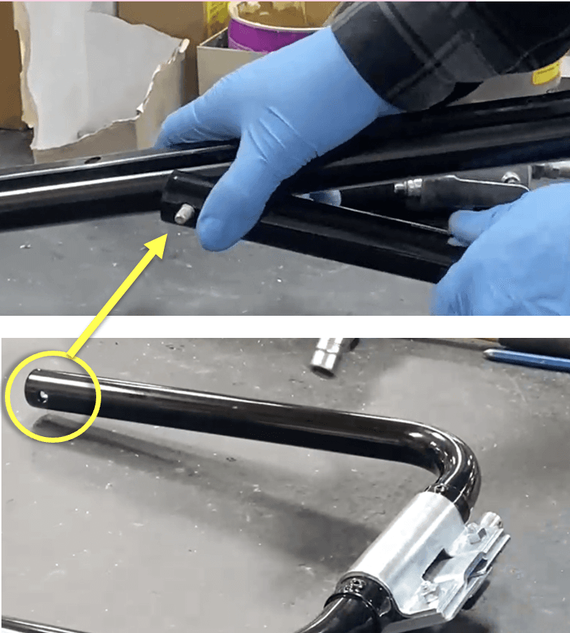
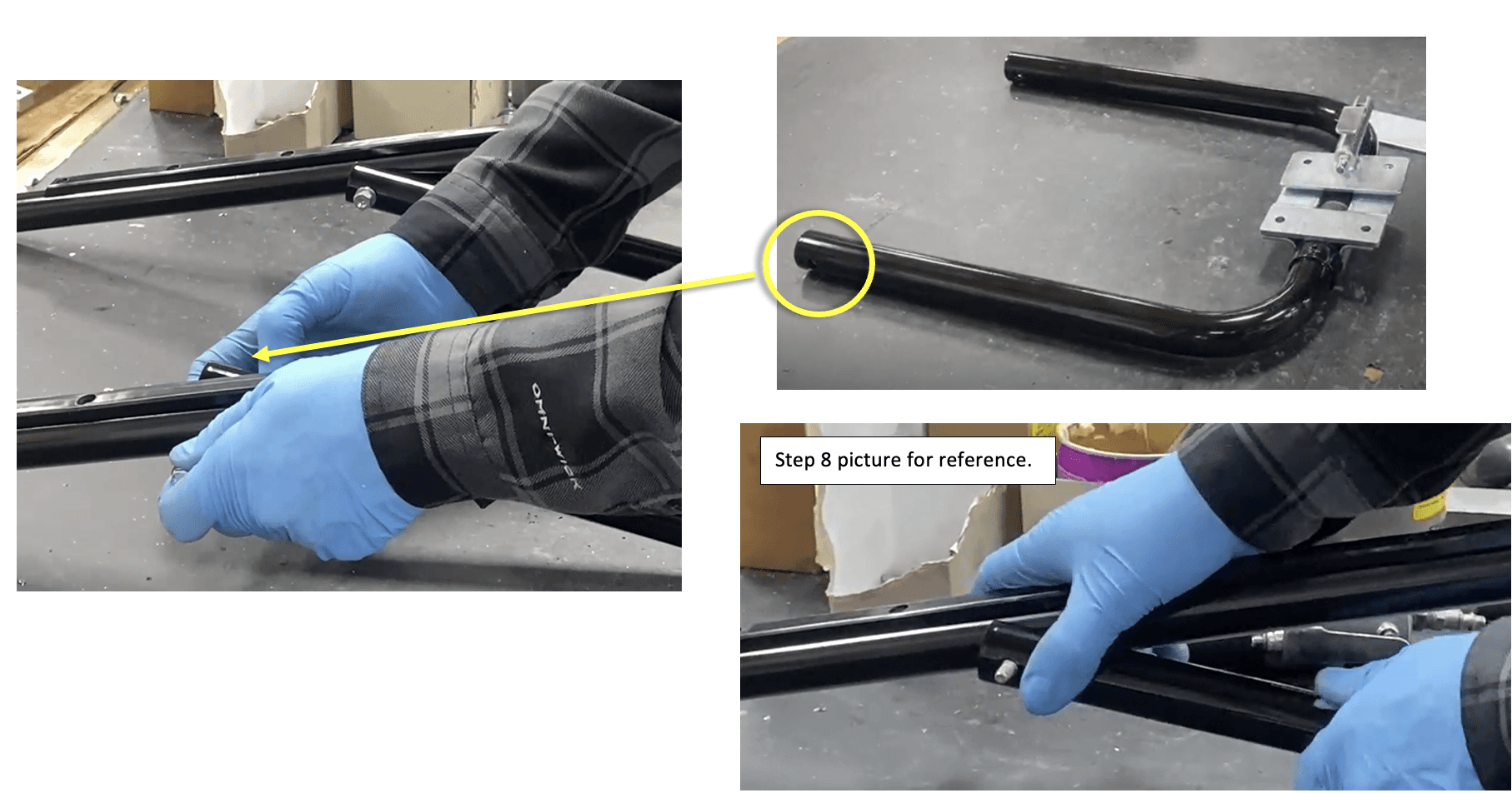
On the other side of the leg frame, insert the washer/sleeve screw combination (refer to step 4) into the remaining leg frame hold, pointing to the center. Do not push it through the brace’s hole yet. Push the screw in only so that there is about a centimeter of extruding screw from the frame hole.
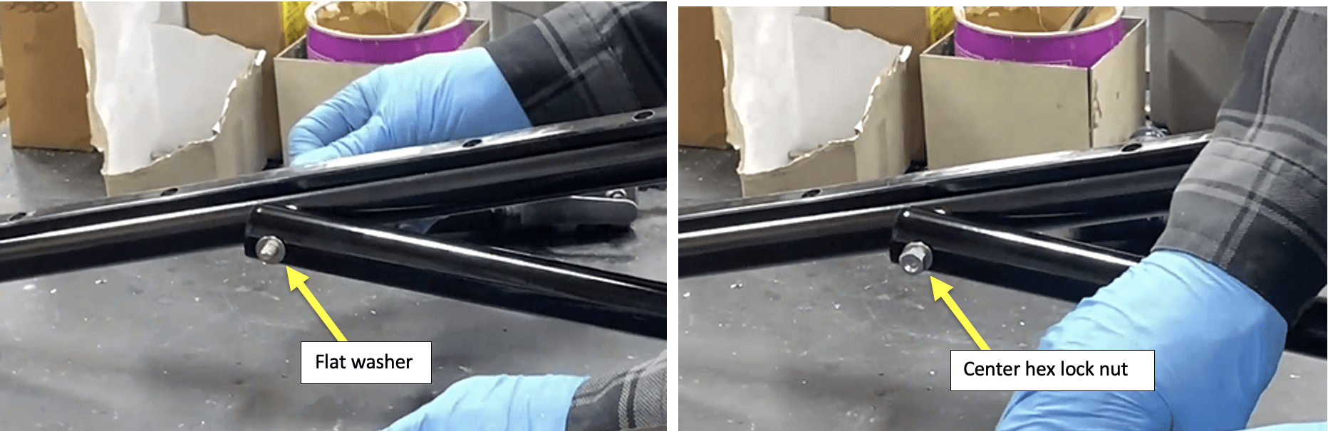
Place a 385-2500 (.688 X .344 X .063 Flat .313 SAE flat washer) onto the extruding screw, as seen in step 7
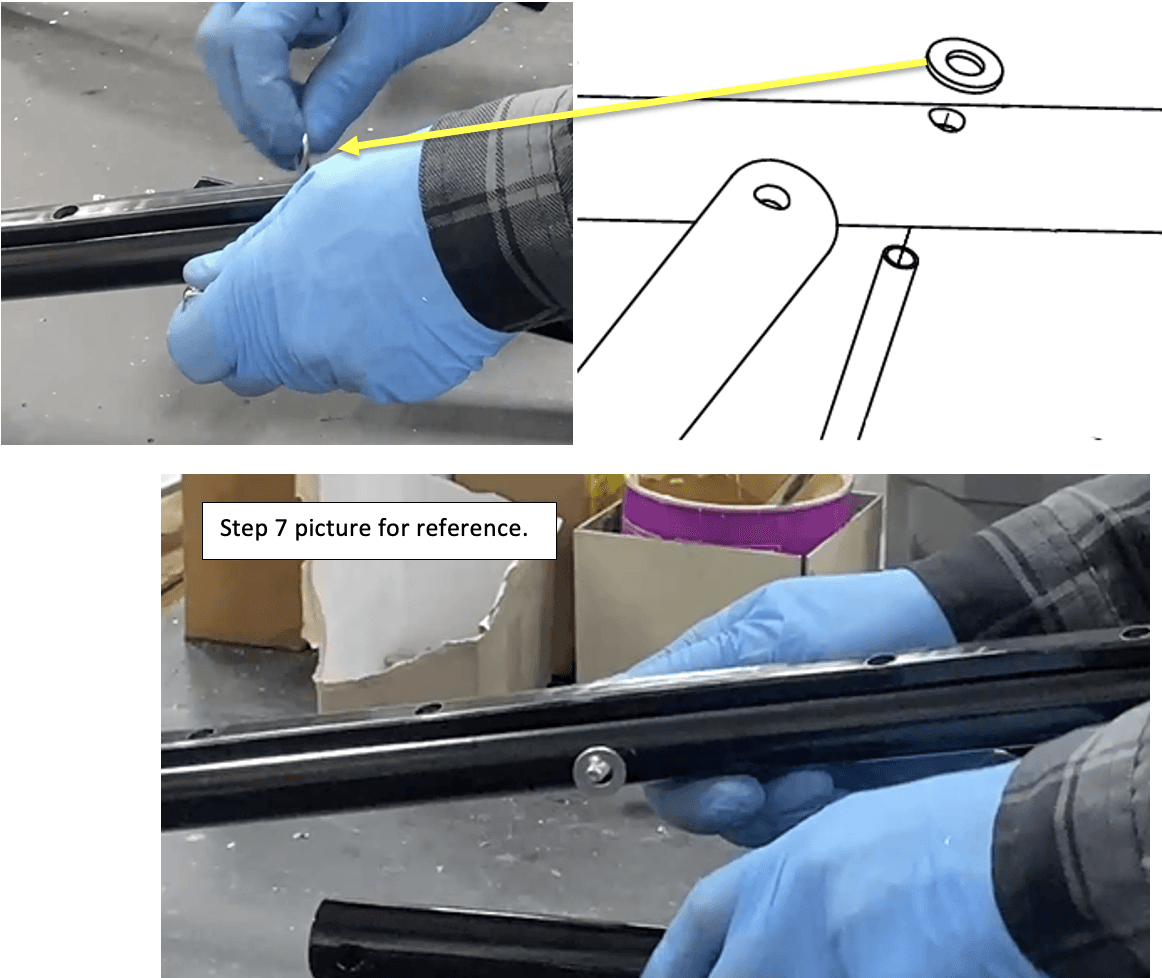
Following the SAE flat washer, place the second end of the operator end leg brace on the extruding screw (via the through hole on the end of the brace), as seen in step 8. (The washer should be between the leg frame and brace.)
You may have to push the extruding screw out to align the holes, then push the remaining screw through the leg.
Place a 385-6118 (.563X .255X .040 flat washer) on the extruding screw from the leg brace, followed by a 3301700 (.250-20 center hex Lock nut), as seen in step 9.
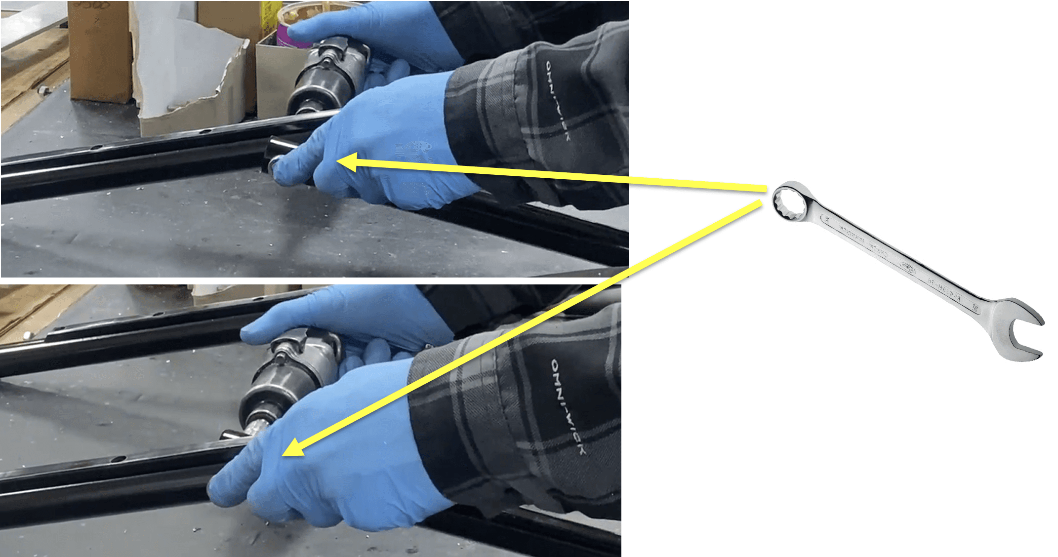
Use a power ratchet and a combination wrench on the cap screw and the lock nut to secure them around the frame and brace. Perform this on both sides. (Size .250-20 for both power ratchet and combination wrench).
Apply blue 242 Loctite to the center hex lock nuts. Perform on both sides.
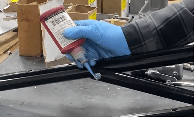
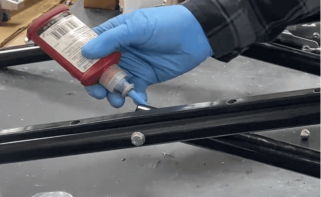
Place a 3301700 (.250-20 Acorn alum nut) onto each of the extruding center hex lock nut. Use a combination wrench to tighten it on.
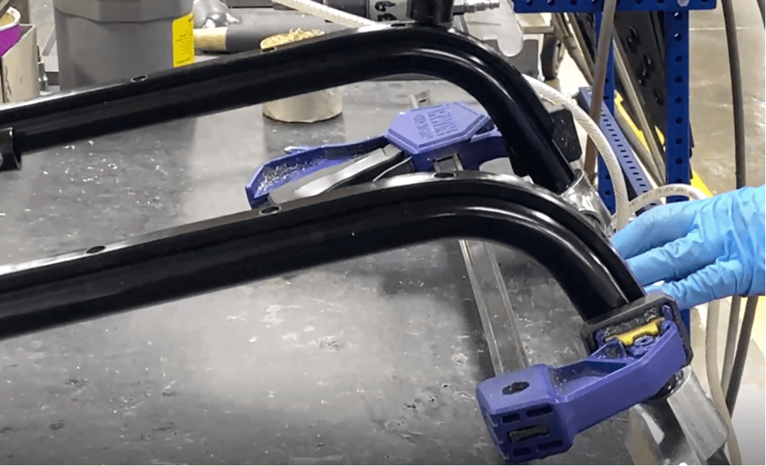
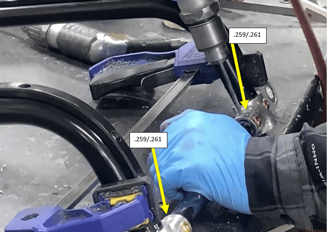
Clamp a C-clamp around the ends of the leg frame like so:
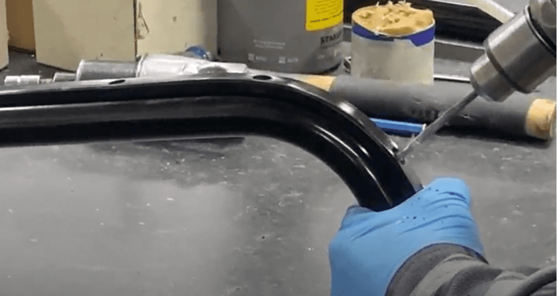
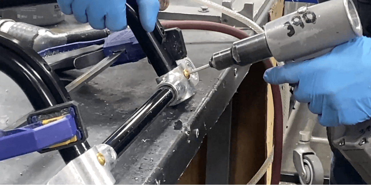
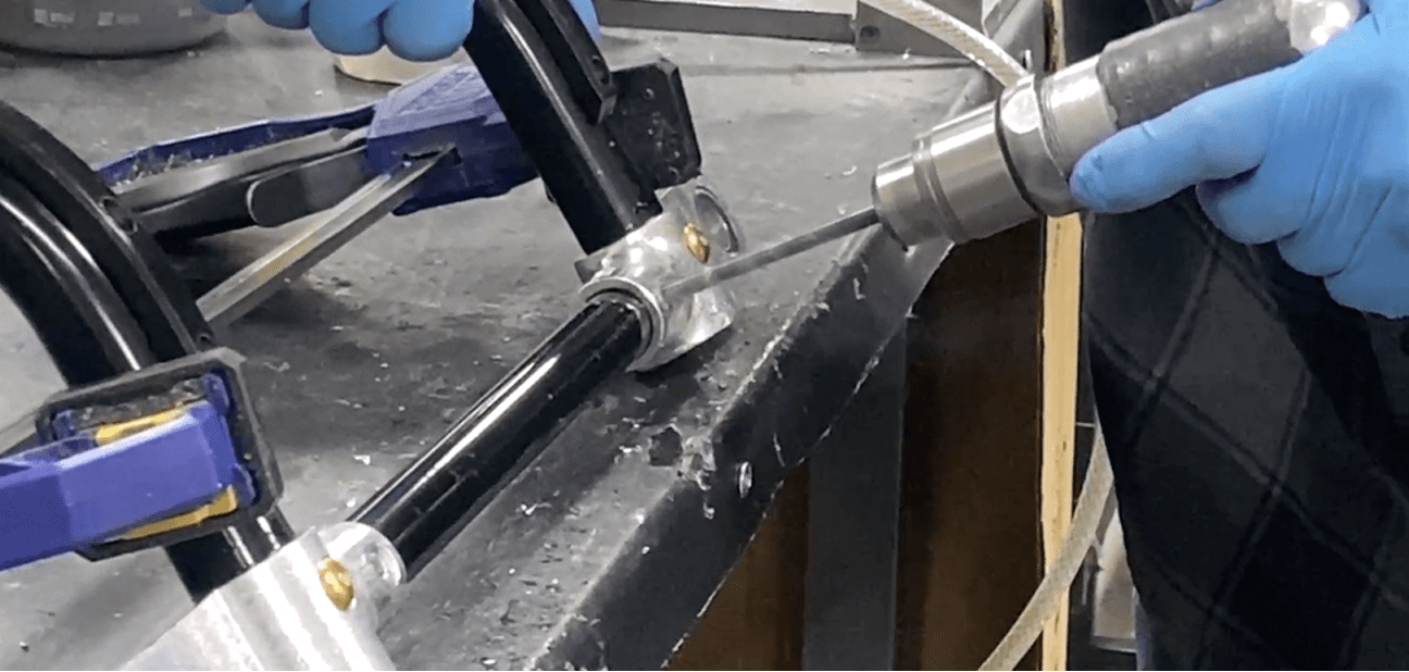
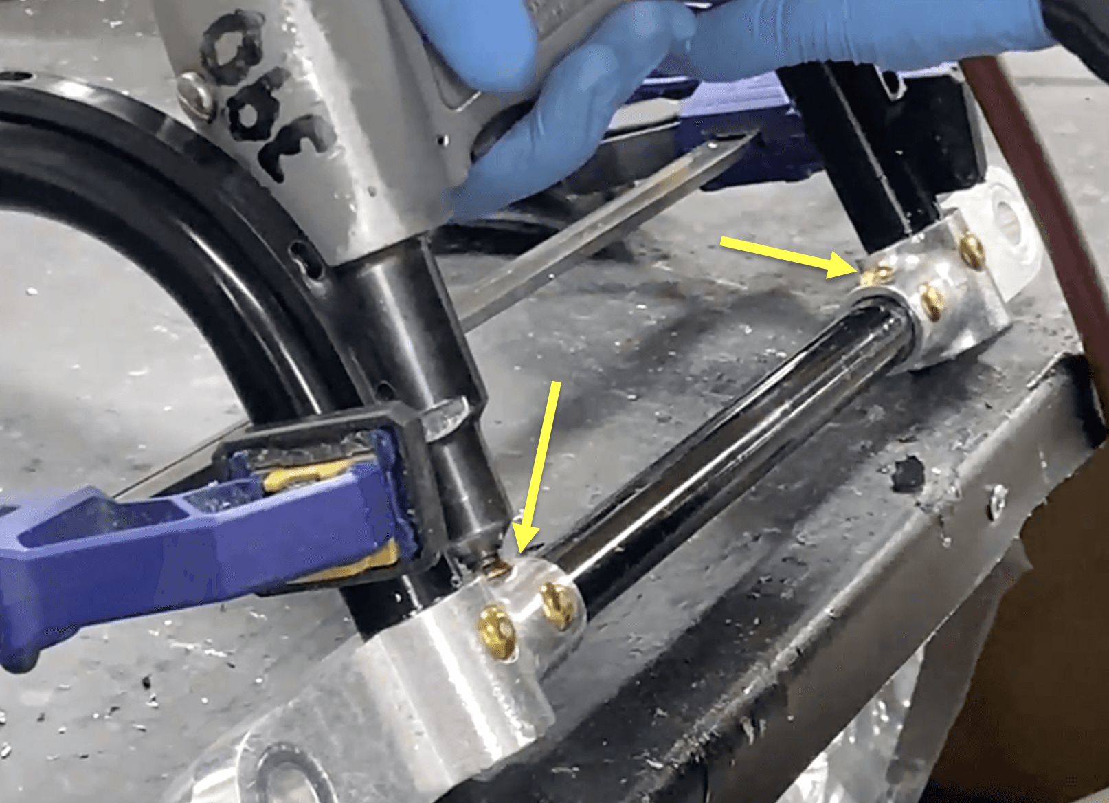
Drill with a size .259-bit into all four of the existing holes on the side of the corner mounts facing you. Drill though one wall only of the cross tube (not through entire tube).
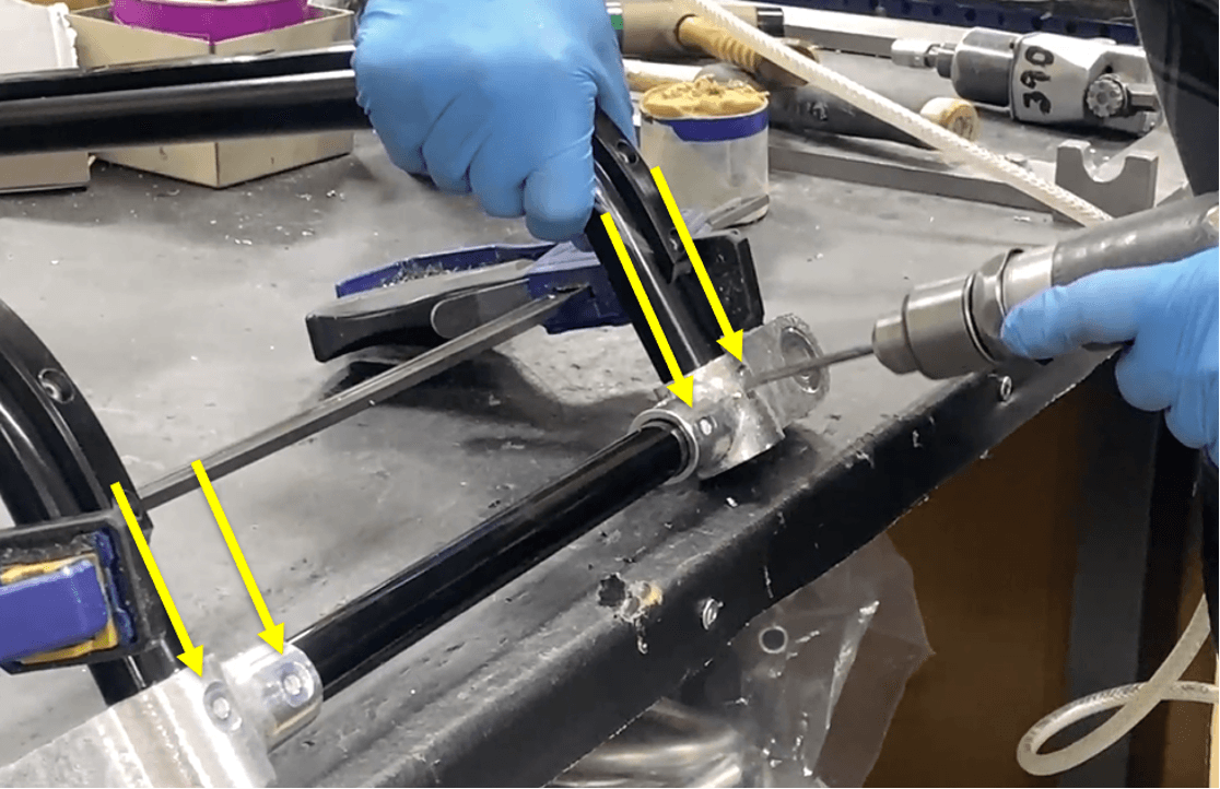
Drill through the two outer holes with a size .261-bit to widen them.
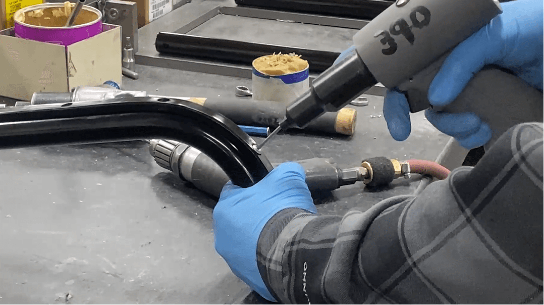
Place two 3405486 (.250 MBCP-R8-M9 huck rivet) into the two outer holes. Use a pop rivet gun to secure the rivets.
Drill through the two inner holes with a size .261-bit to widen them.
Place two 340-5501 (.250 MBCP-R8-M7 huck rivet) into the two inner holes. Use a pop rivet gun to secure the rivets.
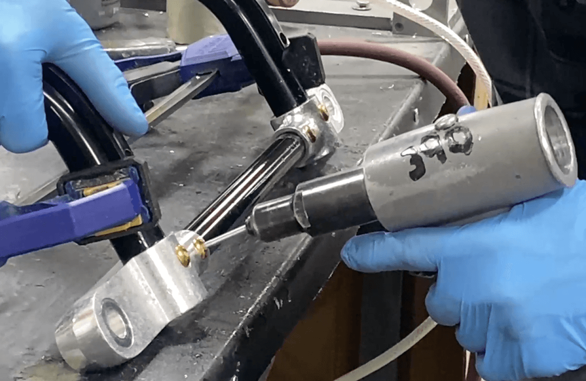
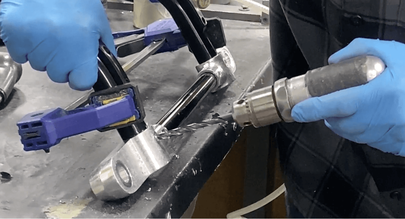
Drill with a size.259-bit size into the two remaining existing holes on the top of the corner mounts (90o away from the inner drilled holes). Drill through one wall only of the cross tube (not through entire tube). Drill again with a size .261-bit size.
Place another two 340-5501 (.250 MBCP-R8-M7 huck rivet) into these two holes. Use a pop rivet gun to secure the rivets.
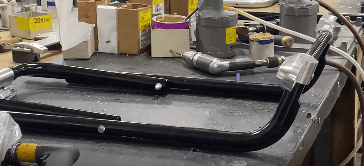
Remove the C-clamp. Flip over and reorient the subassembly as shown.
Drill with a size.259-bit size into the two remaining existing holes; they are the ones facing upwards. Drill through one wall only of the cross tube (not through entire tube). Drill again with a size .261-bit size.

Place another two 3405486 (.250 MBCP-R8-M9 huck rivet) into these two holes. Use a pop rivet gun to secure the rivets.
Flip over and reorient the subassembly as shown.
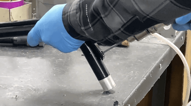
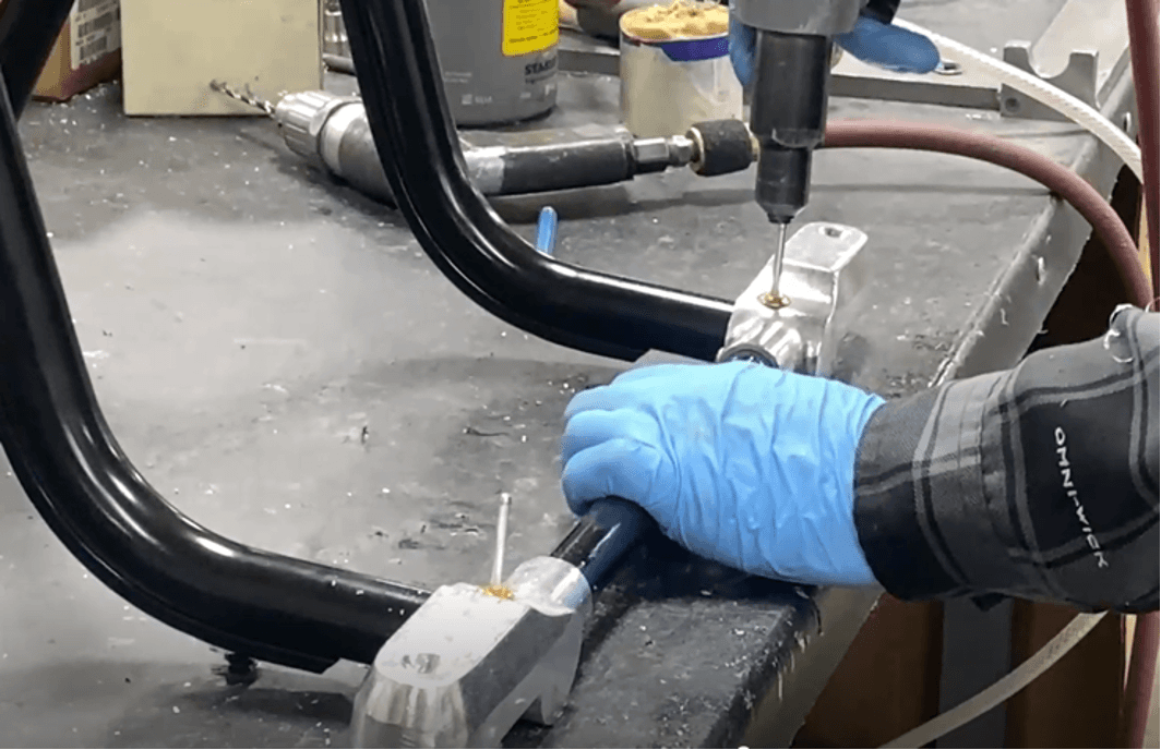
Apply Loctite primer 7649 (690-4579) and red 262 Loctite onto two 3204625 (.250-20X .750 Flat head machine screws (FHMS SKT 4140)).
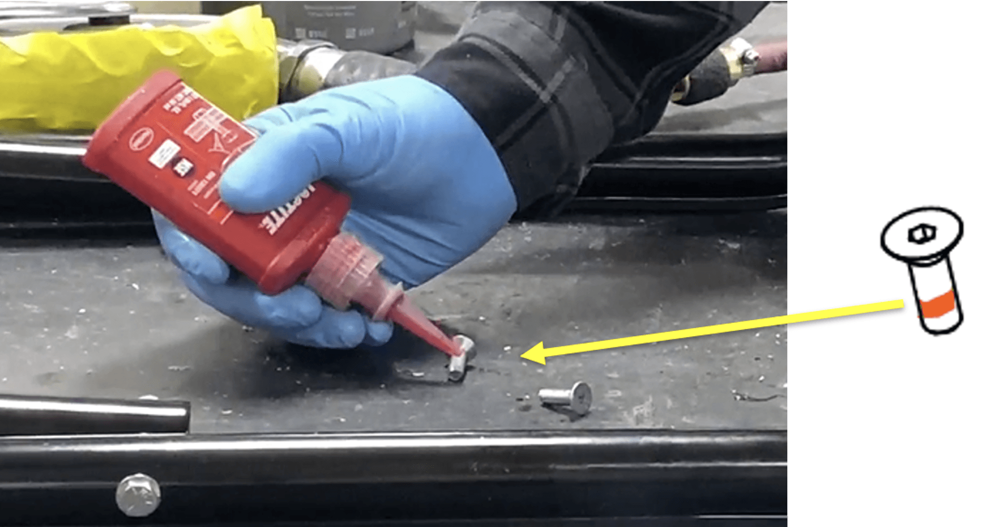
Place the two flat head machine screws and 152-5003 Wheel assembly (“Caster, With Brake”) into the remaining holes of the corner mount.
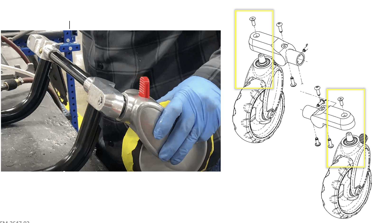
Use a power drill to secure the flat head machine screw (.250 diam.) and wheel assembly into place
Perform steps 30 and 31 to the other corner mount.