
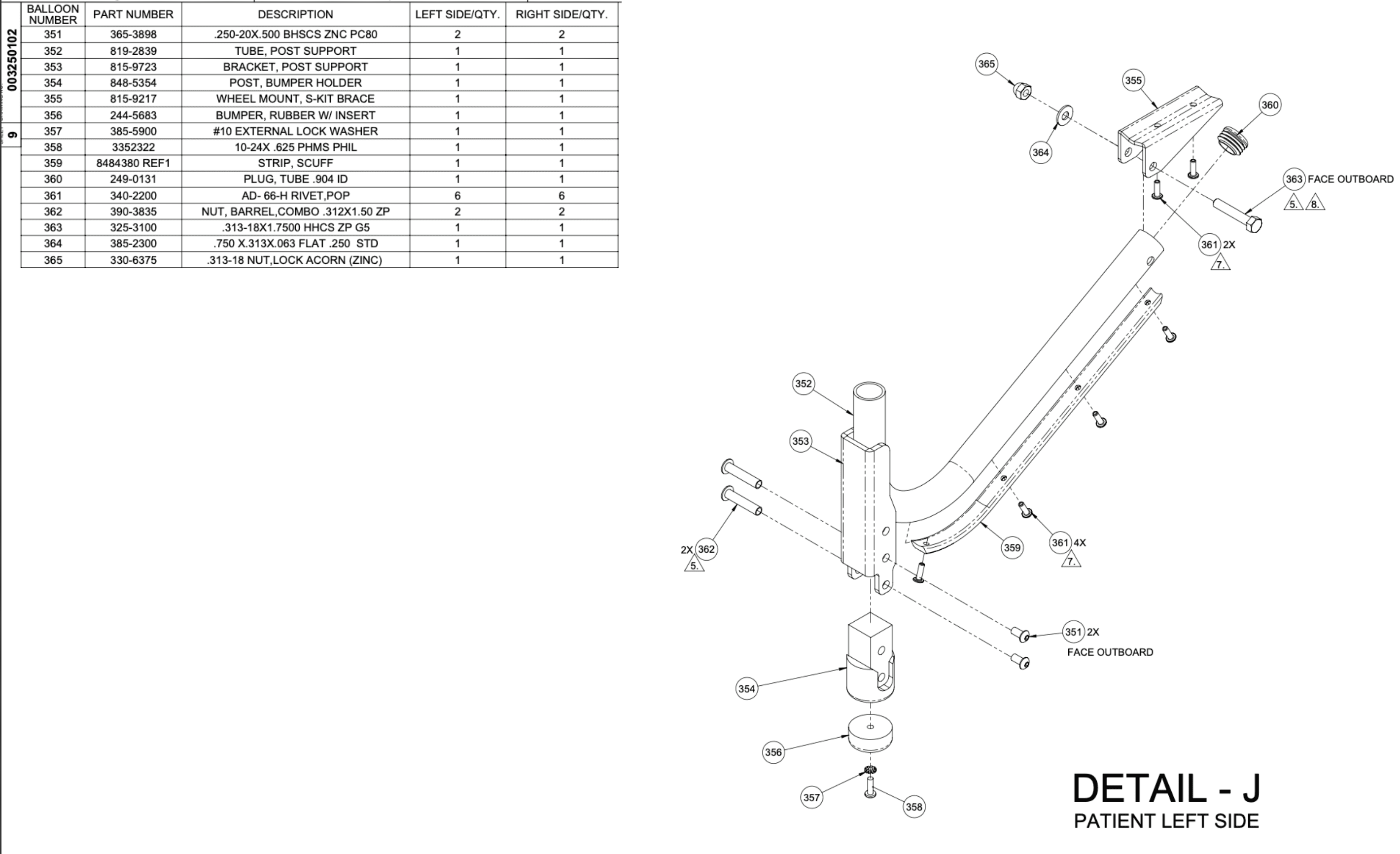
Detail J & Detail K (Post Bracket)
Pop Rivet Gun
Mallet
Screwdriver
8484380 REF1 (Strip, Scuff)
819-2839/815-9723 (Tube, Post Support/Bracket, Post Support).
340-2200 (AD-66-H Rivet, Pop)
819-2839 (Tube, Post Support)
244-5683 (Bumper, Rubber w/ Insert)
848-5354 (Post, Bumper Holder).
385-5900 (#10 External Lock Washer)
3352322 (10-24x .625 PHMS PHIL).
815-9723 (Bracket, Post Support)
390-3835 (Nut, Barrel Combo .312X1 .50 ZP)
365-3898 (.250-20X 500 BHSCS ZNC PC80)
Take part number 8484380 REF1 (Strip, Scuff) and place on bottom side of part number 819-2839/815-9723 (Tube, Post Support/Bracket, Post Support).
a. Ensure to line up the holes on both parts. b. Ensure the orientation of the scuff strip: the chamfered/pointed end should point towards the post tube.

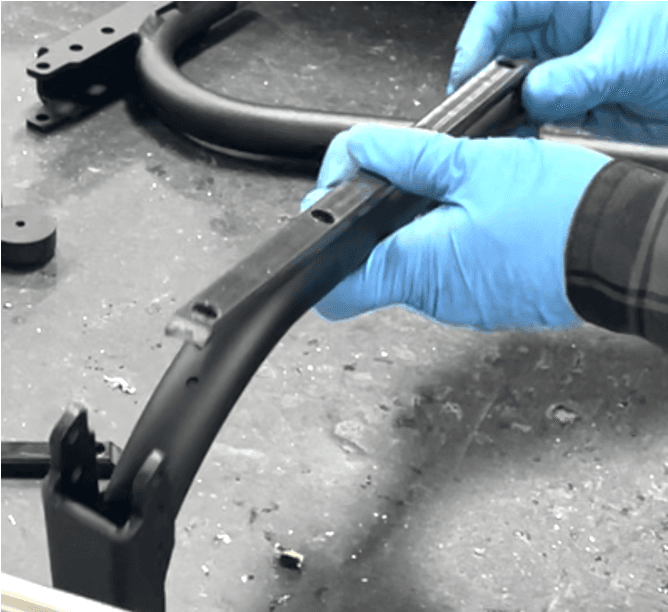
Put part number 340-2200 (AD-66-H Rivet, Pop) in each of the three holes on the flat part of part number 819-2839 (Tube, Post Support).

Use the Pop Rivet Gun to set the three rivets.

4. Place a fourth part number 340-2200 (AD-66-H Rivet, Pop) in the fourth hole on the curved part of part number 819-2839 (Tube, Post Support).

5. Use the Pop Rivet Gun to set the fourth rivet.

6. Repeat steps 1-5 to create a second post bracket/tube subassembly

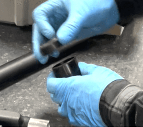
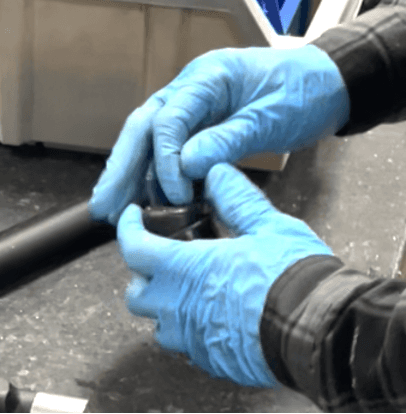
Place part number 244-5683 (Bumper, Rubber w/ Insert) inside circular end of part number 848-5354 (Post, Bumper Holder).
Secure part number 244-5683 (Bumper, Rubber w/ Insert) by hitting the top with a mallet.

Repeat steps 7-8 for the second subassembly.
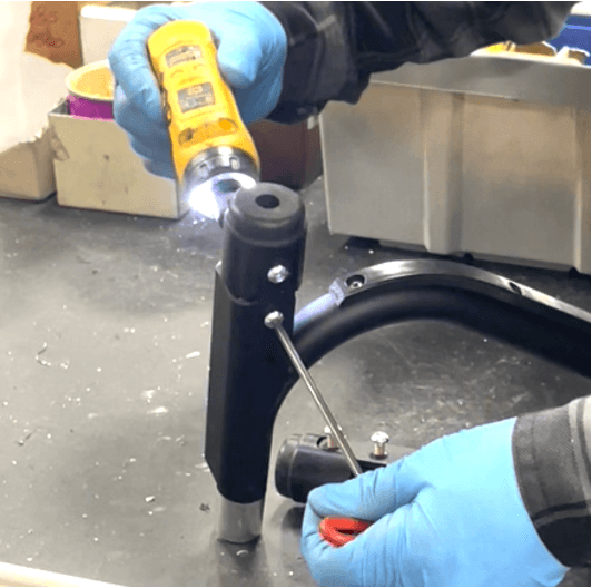
Slide part number 385-5900 (#10 External Lock Washer) onto part number 3352322 (10-24x .625 PHMS PHIL).
Use screwdriver (yellow) to screw parts from step 10 into hole at the top of part number 244-5683 (Bumper, Rubber w/ Insert).

Repeat Steps 10-11 for the second subassembly.
Place part number 848-5354 (Post, Bumper Holder) into part number 815-9723 (Bracket, Post Support) for both sides.
Insert with holes lined up.

Take part number 390-3835 (Nut, Barrel Combo .312X1 .50 ZP) and place it into the top hole that lines up with where the Bumper Holder Post was just inserted on part number 815-9723 (Bracket, Post Support).
Apply Blue Removable Thread locker? Not seen in video

Hit Barrel Combo Nut with mallet until it is fully in the hole.

Repeat Steps 14-15 for the hole directly under the top hole.

Repeat steps 14-16 for the other side.
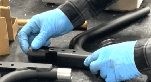
Flip over both assemblies
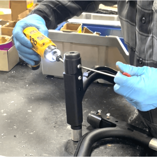
Place two of part number 365-3898 (.250-20X 500 BHSCS ZNC PC80) in the same holes facing outboard.
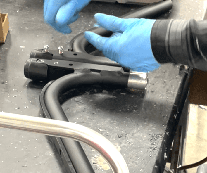
Using a screwdriver, screw both of part number 365-3898 (.250-20X 500 BHSCS ZNC PC80) into place

Use another screwdriver on the other side of the assembly to ensure parts are secure
Repeat steps 19-21 on the other side.
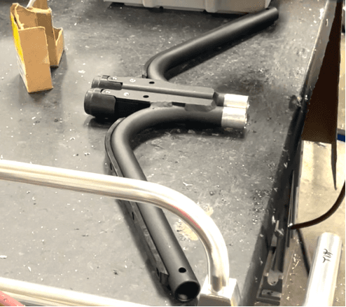
Put both assemblies together and wrap the bottom in yellow tape