
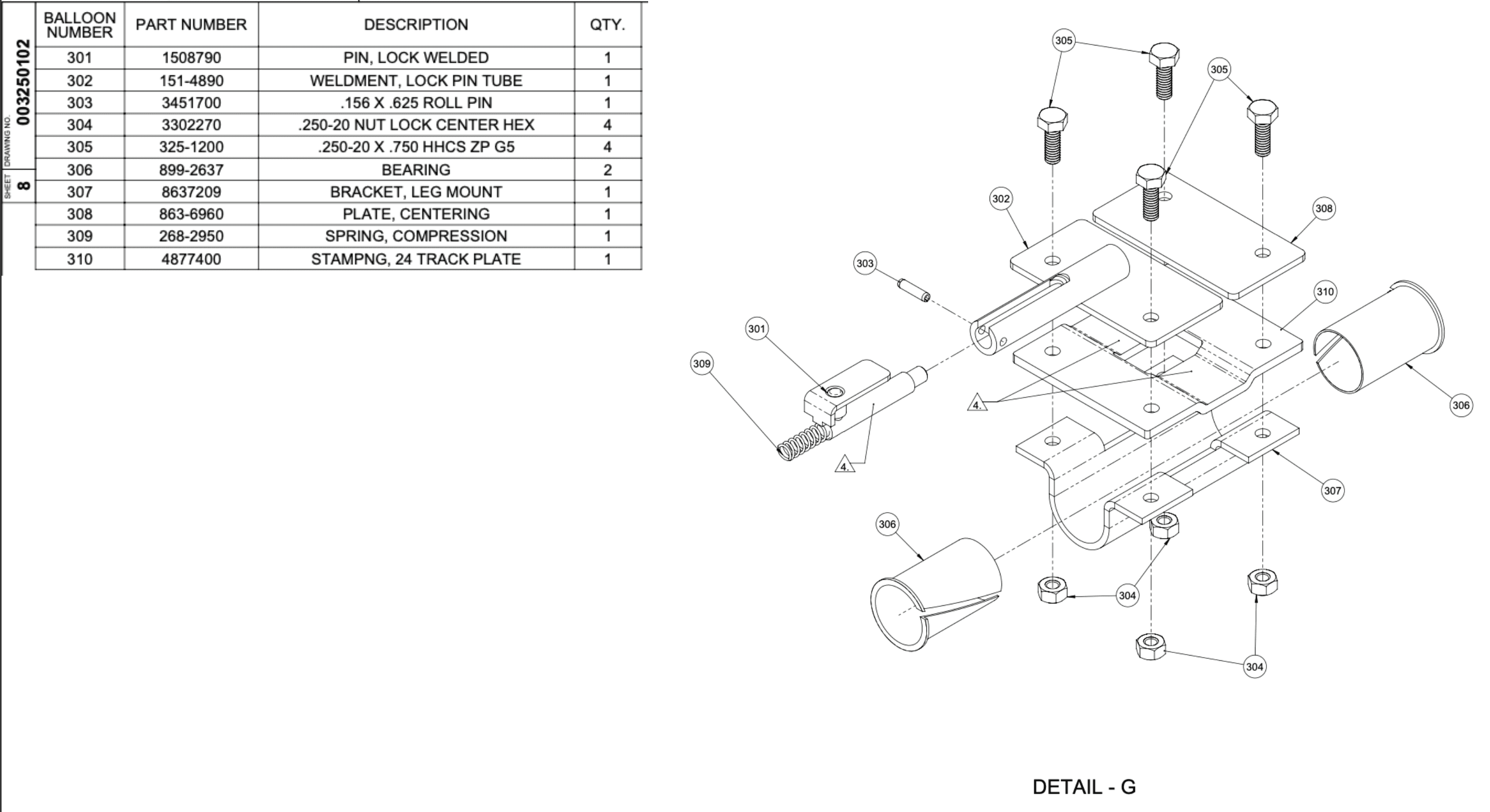
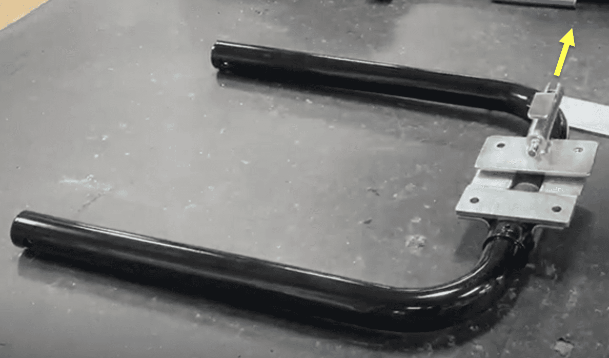
Detail G (Operator End Leg Brace)
Wrench
Power Ratchet
Operator end leg brace (1525352)
two bearings (889-2637)
leg mount bracket (8637209)
24-track plate stamping (4877400)
centering plate (863-6960)
lock pin tube weldment (151-4890)
lock welded pin (1508790)
compression spring (268-2950)
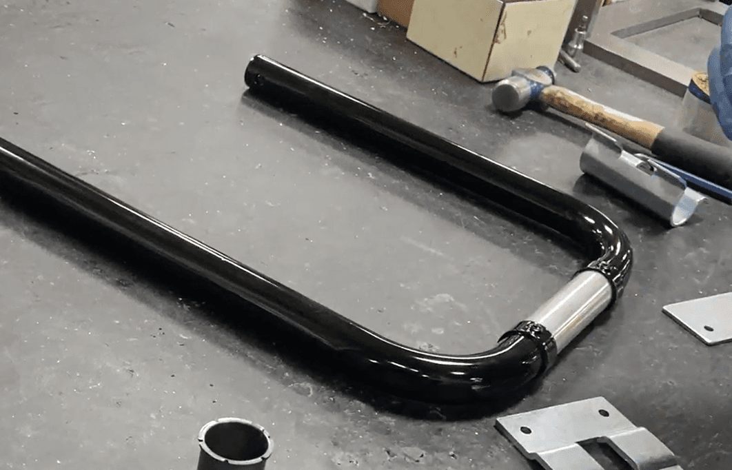
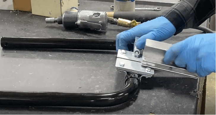
Place the 1 Operator end leg brace (1525352) in front of you, oriented to look like a “U.”
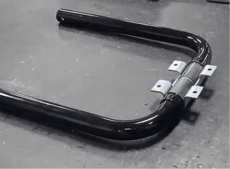
Place two bearings (889-2637) onto the operator end leg brace between the two corners.

Place leg mount bracket (8637209) under/around the bearings and brace so its curved side is between the brace and the table.
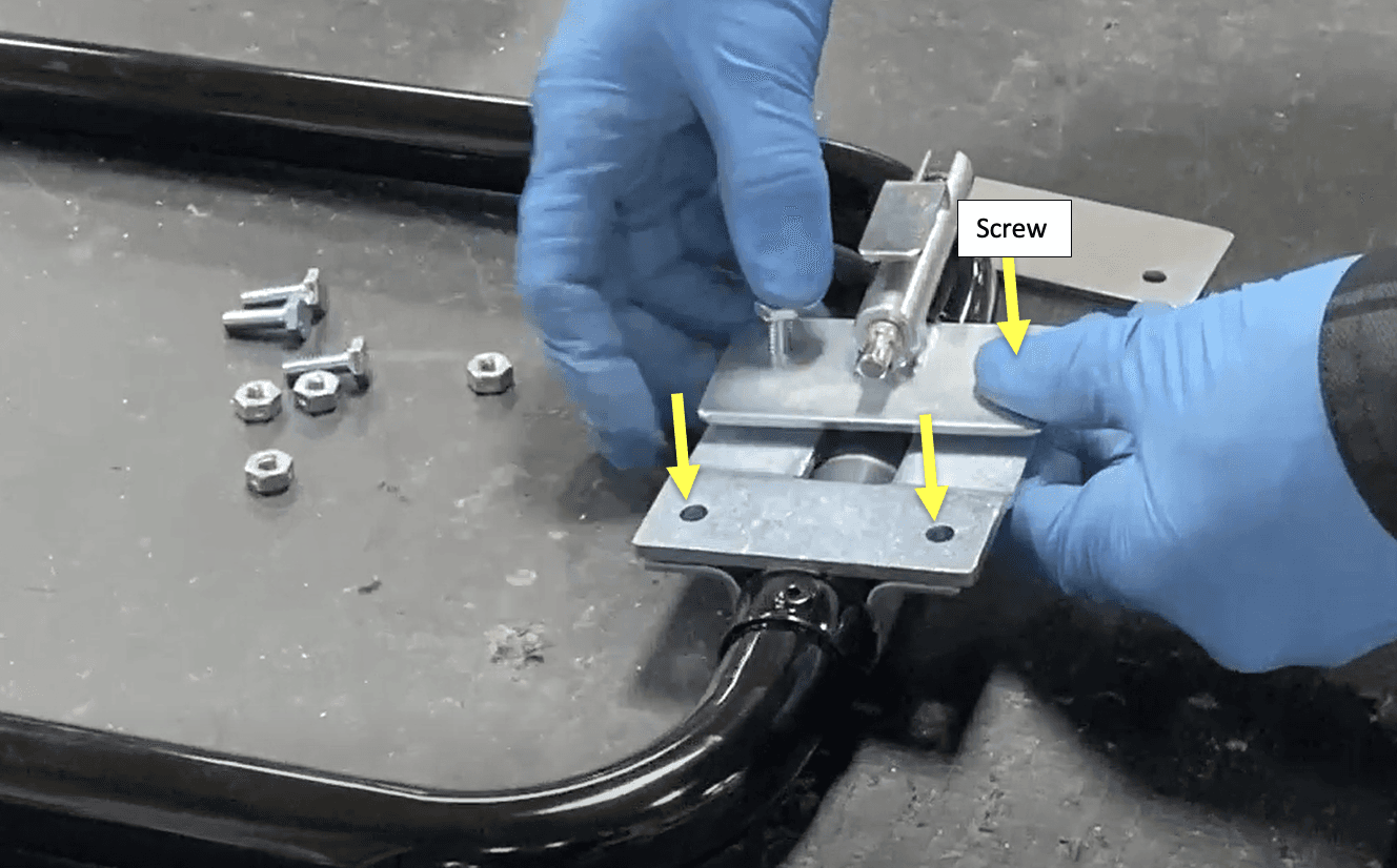
Place a 24-track plate stamping (4877400) on top/other side of the brace, so the holes align with the leg mount.
a. Verify the orientation: the track plate should end up flush with the bracket, with the bearings/brace snug between them. Refer to the picture.

Place a centering plate (863-6960) on the left side and atop the track plate (holes align). Place a lock pin weldment subassembly (lock pin tube weldment 151-4890 + lock welded pin 1508790 + compression spring 268-2950) on the right side, tube pointing outwards, and atop the track plate (holes align).
Place .250-20 X. .750 HHCS ZP G5 (3251200) screws (qty. 4) into the aligned 4 holes starting from the top centering plate and lock pin tube weldment.
Use Center hex lock nut .250-20 (3302270) (qty. 4) to lock it in against the mount face at the bottom.
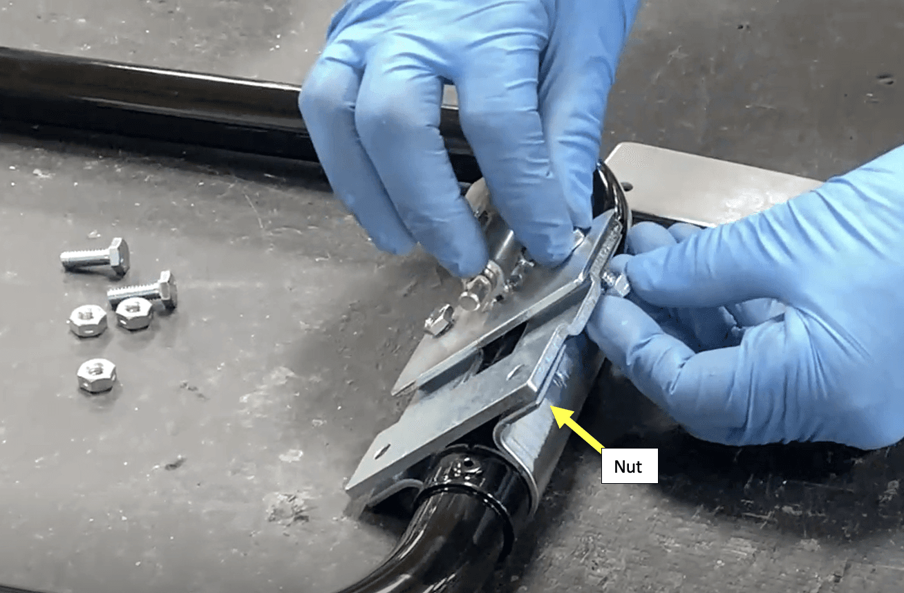
Tighten the screws and locknuts until all pieces are secure around the leg brace. Use either option 1 or 2.
a. Option 1: Hold the nut with a wrench and drill in the screw with a power ratchet.
b. Option 2: Hold the screw with a wrench and drill in the nut with a power ratchet.


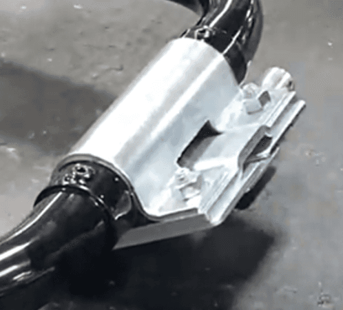
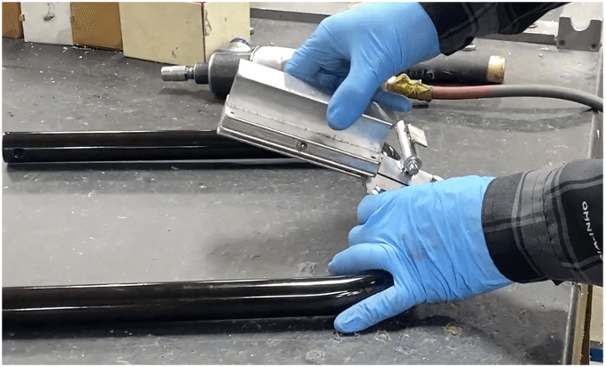
1. Slide the mini I-bar tooling part into the resulting sliver (between the centering plate, lock pin weldment, and track plate) as seen below.
Continue to Detail L