
24 MiniMAXX Cot Final Assembly
Hammer
Mallet
Marking pin
Paint brush
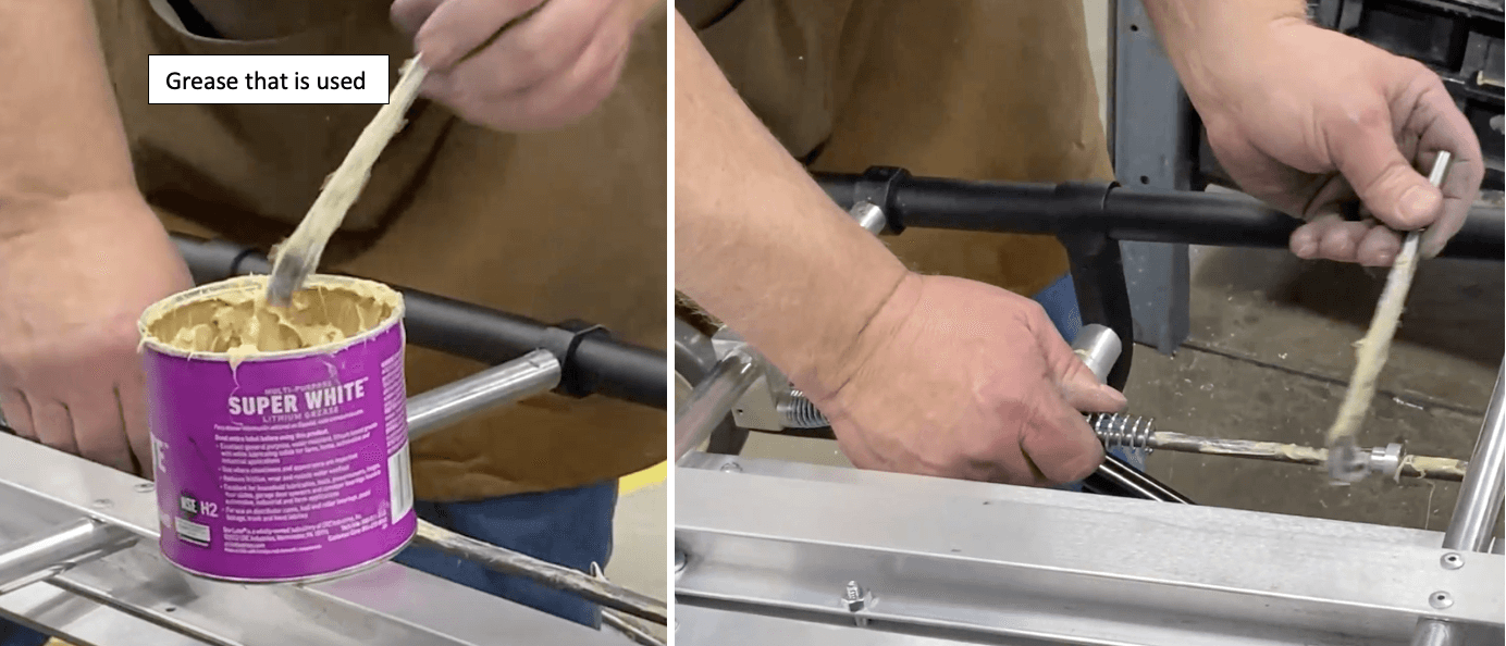
Grease
Black paint
Powered belt sander
Powered Socket Wrench
5/32”
Powered Ratchet
.250
Power Drill
¼” Drill bit
.104/#37
.152
.156
Pop rivet gun
Phillips Head Screwdriver
#4
All Parts in this list
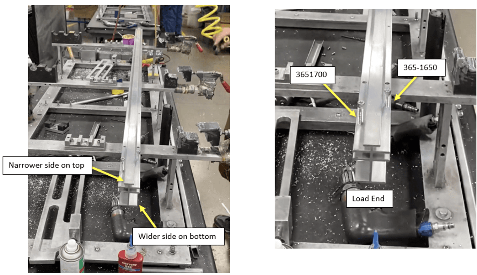
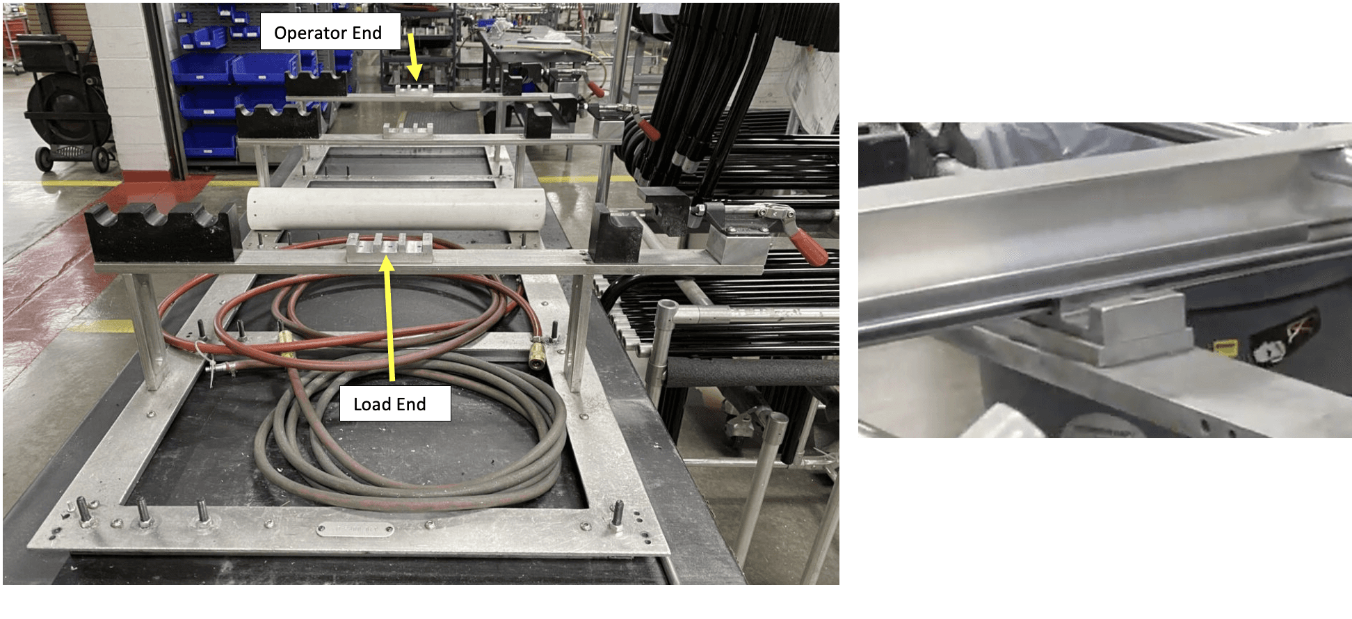
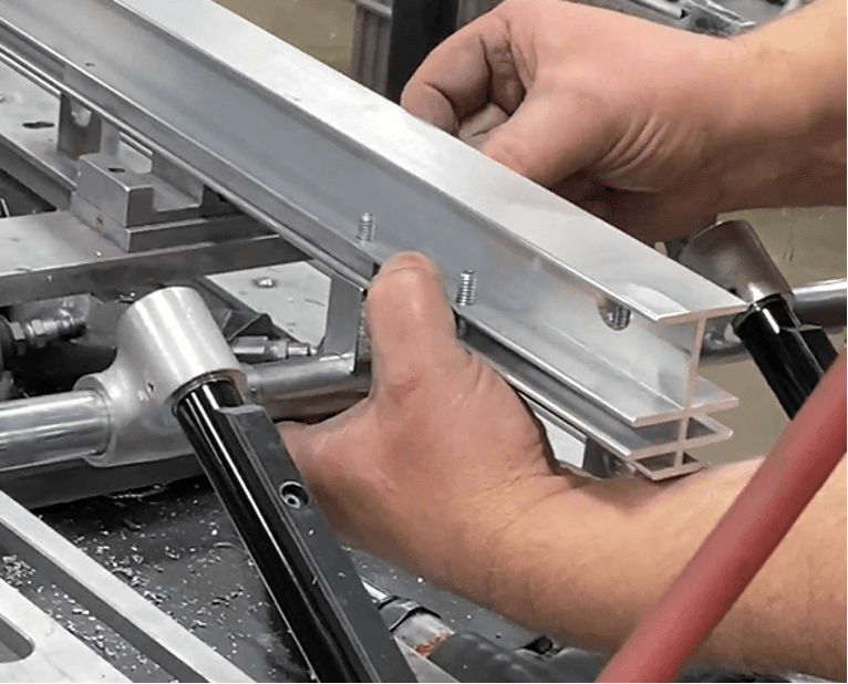
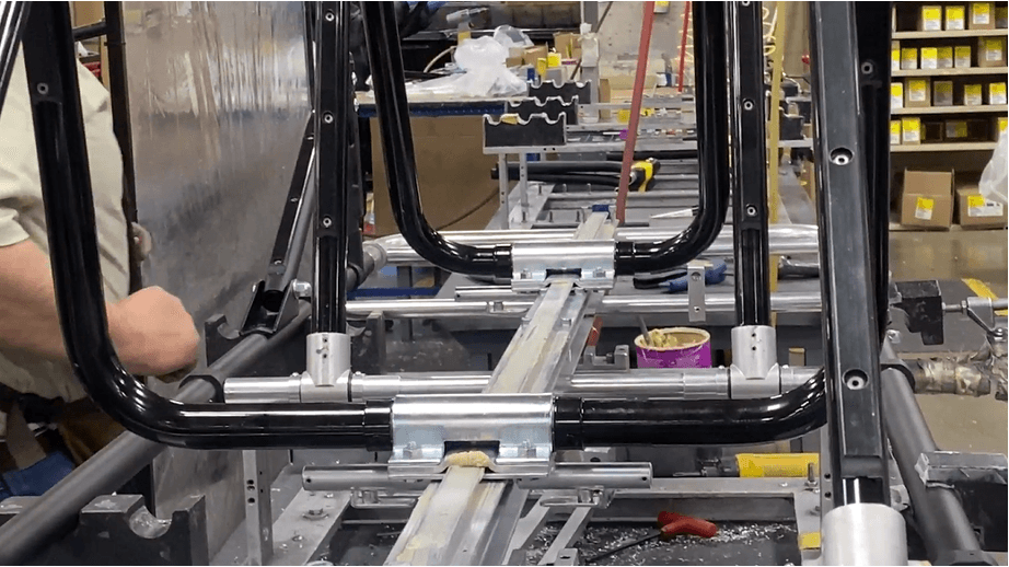
Place 1525362 (I-Beam, W/ Filler Bars) onto fixture 930-0065 (Fixture, 24-series Assy). For now, place the I-beam upside down, the widest layer against the fixture, the narrowest layer on top.
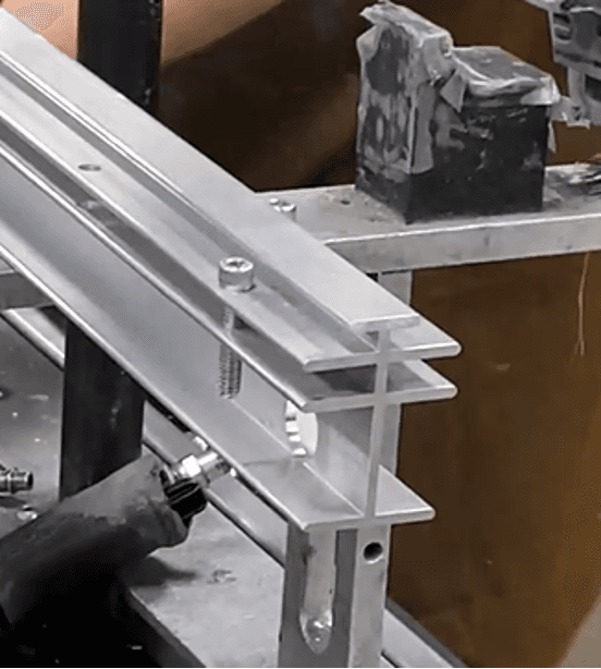
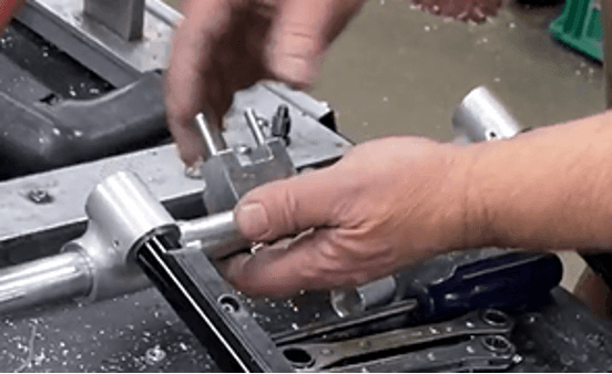
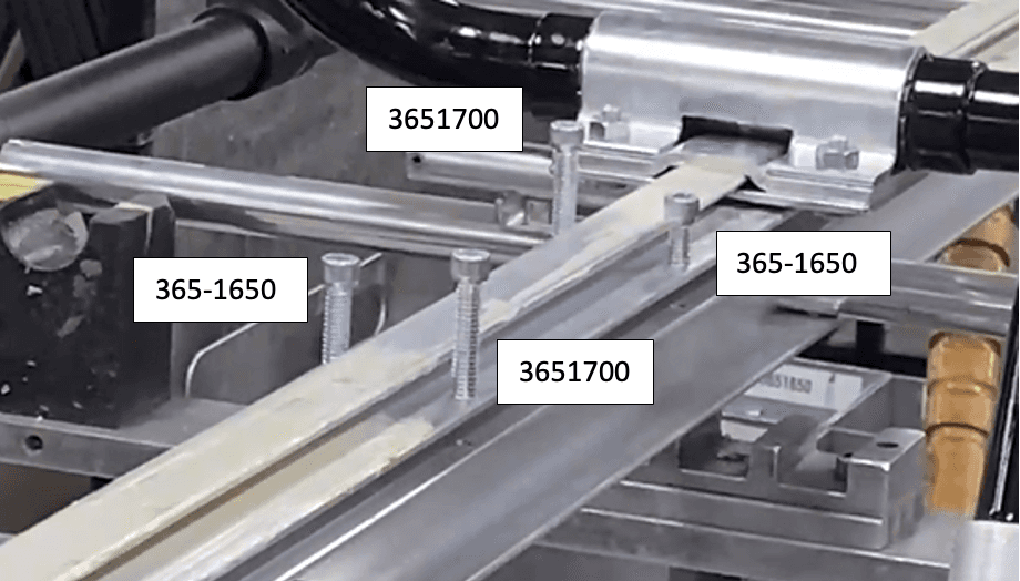
Place 365-1650 (.250-20 X 1.000 Socket Head Cap Screw (SHCS)) and 3651700 (.250-20 X 1.250 SHCS Zinc Grd 8) onto the I-Beam, load end side. Refer to the two holes on the load end side closest to the end.
Of the two end holes, place 365-1650 in the farther one. Place 3651700 in the hole closest to the end.
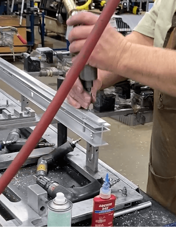
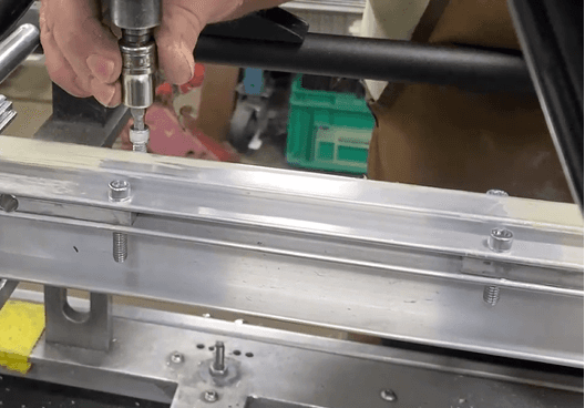
3. Use a powered socket wrench, 5/32” head, to install the two socket head cap screws.
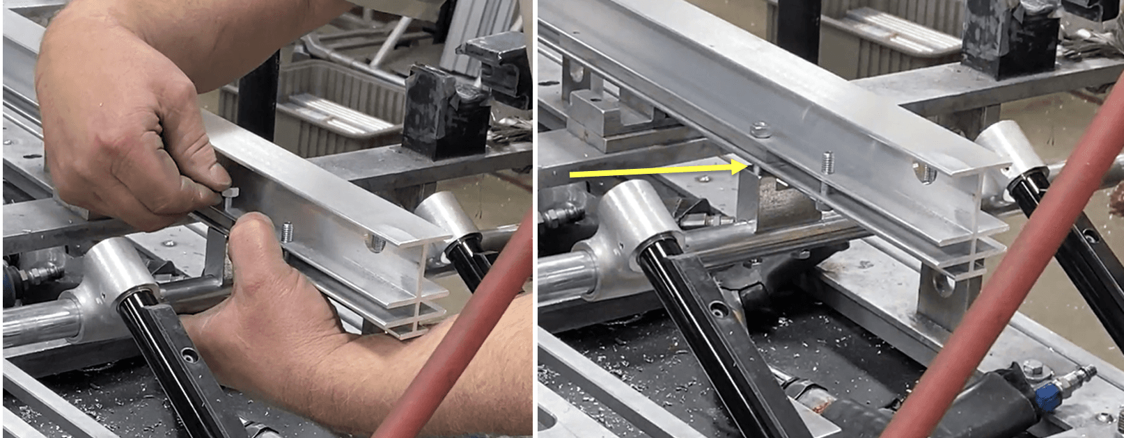
Flip over the I-beam and properly place it into fixture 930-0065 – place the narrower side into the middle wrung.
Insert two 3251700 (.205-20 X 3.000 Hex Head Cap Screw (HHCS) ZP G5) into the two holes in the center of the Load End Leg Brace’s crosstube (See “Load End Leg Brace Subassembly” work instructions).
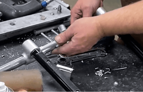
Insert 8097214 (Spacer) onto the two extruding ends of the hex head cap screws. The curved end of the spacer goes in first.
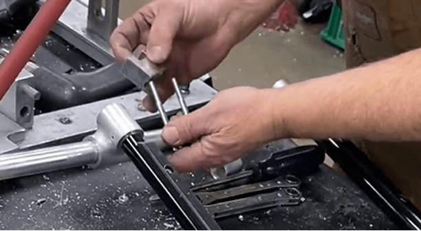
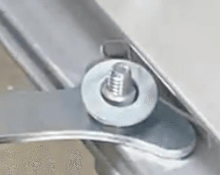
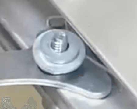
Place the extruding screws through the two holes behind the socket head cap screws until the spacer is flush with the I-beam.
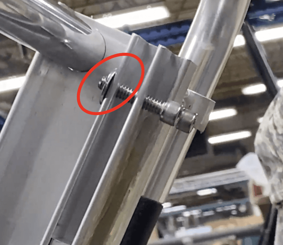
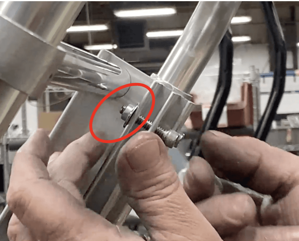
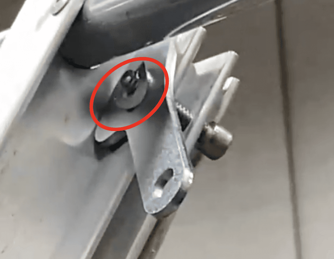
Screw in a 3302270 (.250-20 Nut Lock Center Hex) on the two extruding screws to secure the leg frame subassembly to the I-beam. Tighten just enough so that the subassembly is attached and not falling off from the I-beam – notice the space notated in the picture – this is perfectly acceptable.
Place an 819-2487 (Leg Spacer) on each side of the load end leg frame’s crosstube.
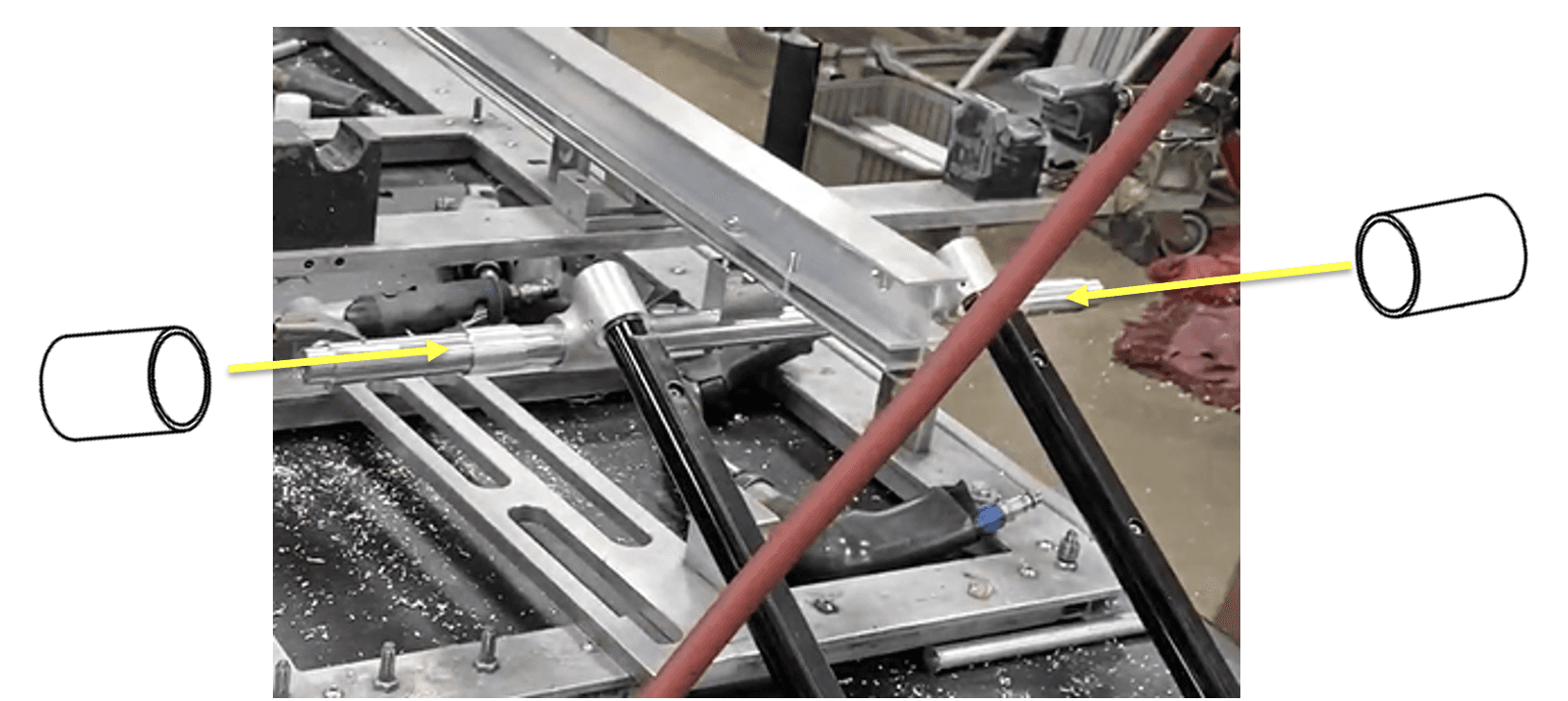
Insert five 819-2486 (.75OD X .58ID X 19.745L X-Tube) into the five circular holes on the inside side the I-beam.
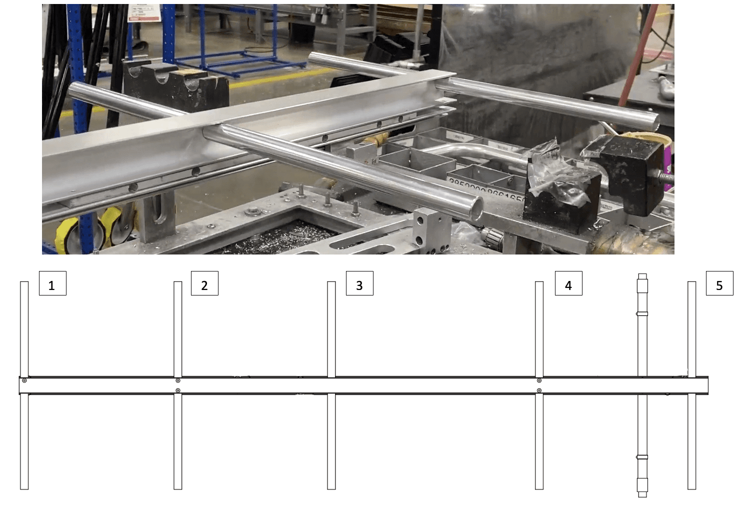
Then insert five 8125078 (X-Tube Stiffener) into each x-tube/crosstube. Insert until the ends are flush.
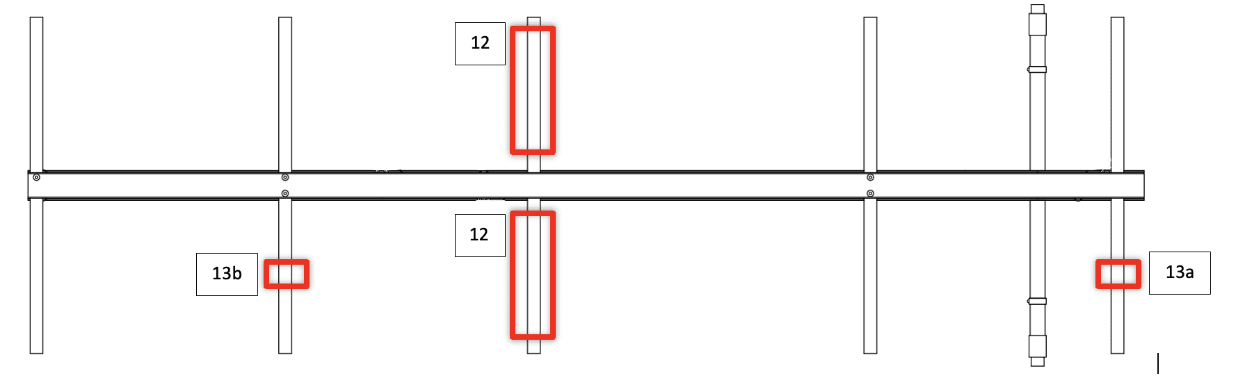
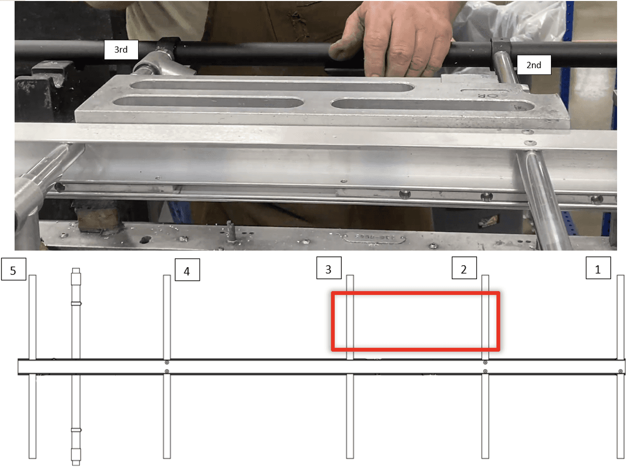
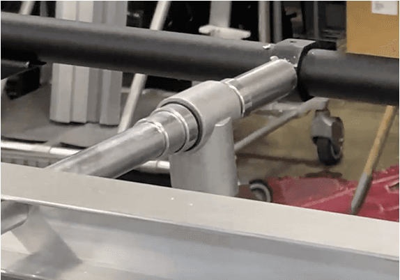
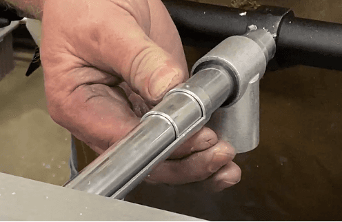
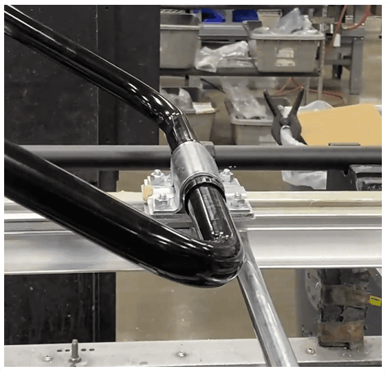
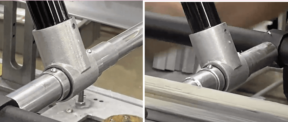
12. Slide a 152-2615 (Weldment-Tee) onto an 819-2098 (.875 X .058 X 5.500 Sleeve). Put an 818-6980 (Ring Spacer) on each side of the Weldment-Tee.
a. Do this twice so there are two sets. Slide the sleeves (with the spacers and weldment-tee) onto each side of the I-beam on the 3rd crosstube (see next page for reference).
b. If not already, put a 204-2727 (Split Nylon Bearing, .875 ID) inside the weldment tee.

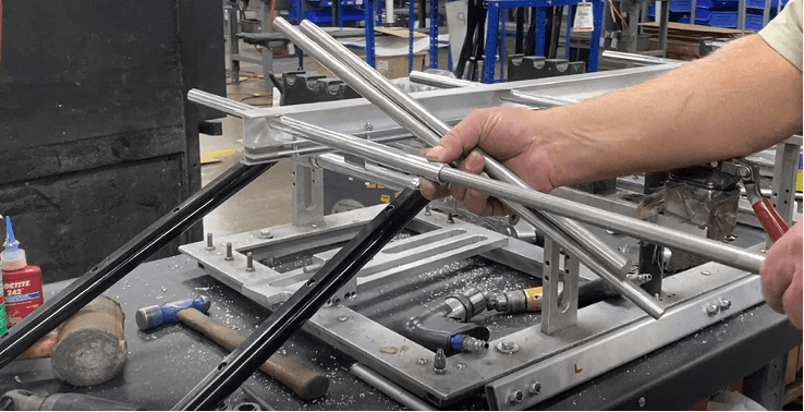
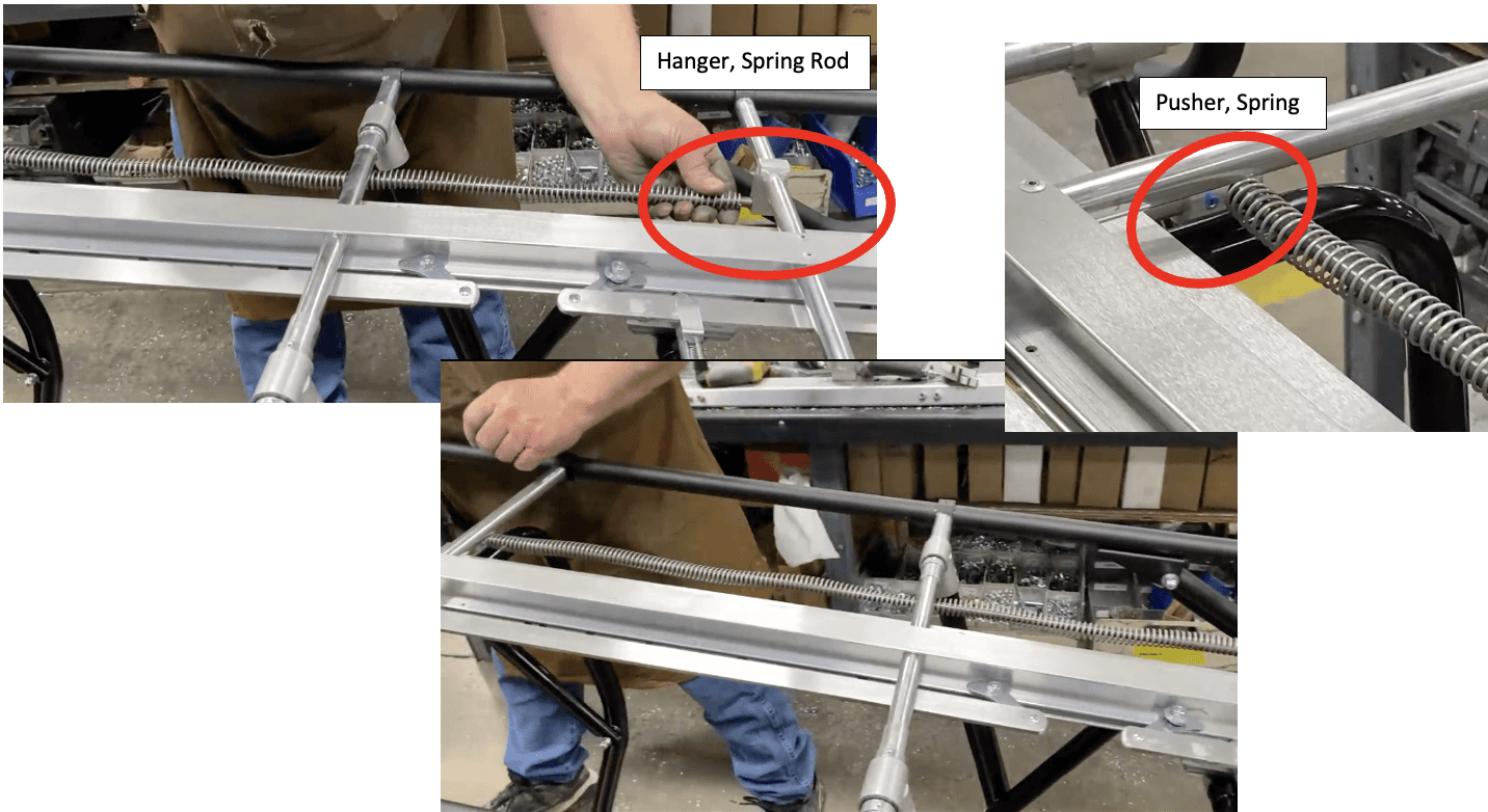
Get two 8093620 (Spring Rod Hanger).
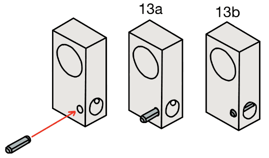
On one, insert 3451700 (.156 X .625 Roll Pin) into the small corner hole just enough that it does not appear through the existing hole. Hammering just ONCE on the roll pin should be enough to secure it so it does not fall out.
Slide this one onto the left side of the I-beam on the 5th crosstube from the operator end.
b. On the second one, fully hammer in the 3451700 roll pin into the small corner hole.
i. Slide this one onto the left side of the I-beam on the 2nd crosstube from the operator end.
Place the 1525356 (Main Half Left Frame) into the second divet on the fixture’s left side. Place the 1525335 (Main Half Right Frame) onto the fixture’s right side, where there is only one divet available. Use the 3 red levers to secure the main right frame.
Starting from the load end, where the loops of the main frames are, align the first four cross tubes AND the leg frame subassembly crosstube to the extrusions on the main LEFT frame. Push the crosstubes onto the main frame’s extrusions.
a. Notice that the last cross tube on the operator end is free.
Hammer/Mallet the other side of the crosstube (right side) to secure them into the left extrusions of the main left frame. Do this for the four cross tubes and leg frame subassembly cross tube that are aligned with the left main frame.
a. Note: You might have to move the right main frame to get access to the crosstubes. It is acceptable to remove the main frame from its notches in the fixture temporarily for this step.
Repeat step 15 and 16 with the other side (align main RIGHT frame with crosstubes).
a. Reminder that the fifth crosstube at the operator end is still free.
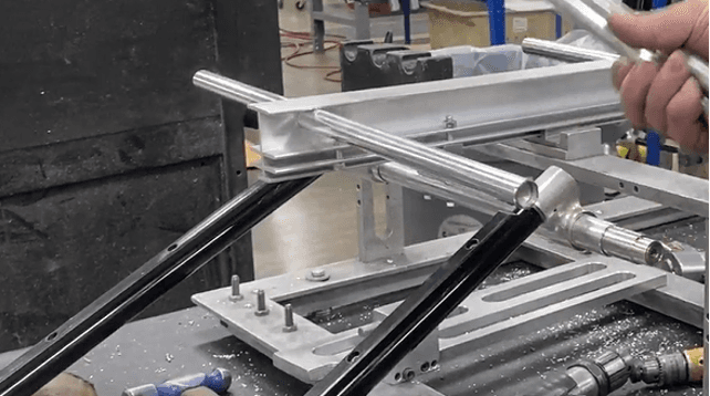
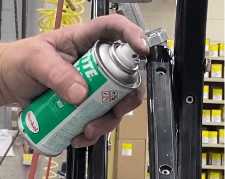
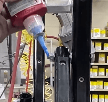
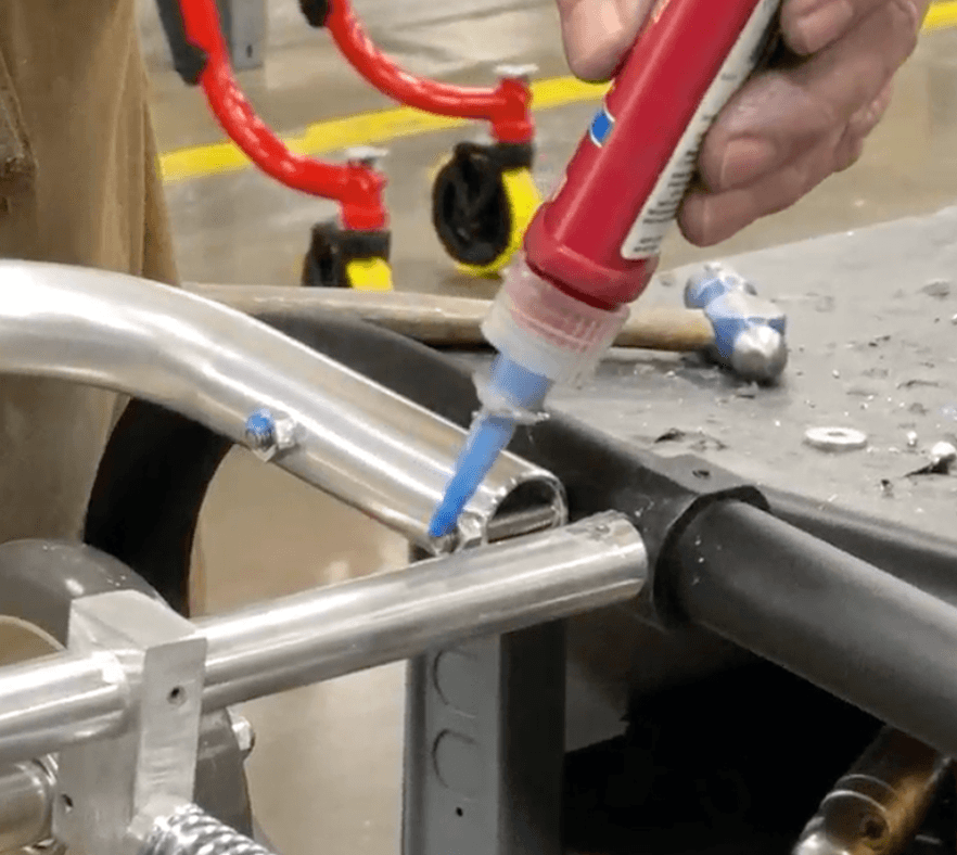
Apply Loctite primer 7649 (690-4579) and blue 242 Loctite onto two 320-3600 (.313-18 X 1.250 Phillips Flat Head Machine Screw (FHMS PHIL)). Blue Loctite position on the screw is depicted in blue.


Install these two 320-3600 (.313-18 X 1.250 FHMS PHIL) into the holes on each side of the main frames aligned with the leg frame subassembly crosstube. Use a #4 Phillips head screwdriver.
Use a power drill with a 1/4” bit to drill into the two existing holes on the top section of the main right frame.
a. This is only due to the paint decreasing the width of the holes; drill through one wall only.
21. Do this on the other side, the main left frame.
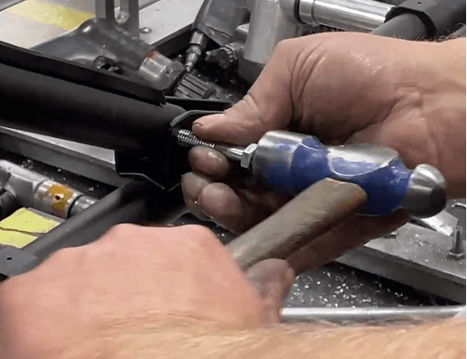
Place a 330-6375 (.313-18 Acorn Lock Nut (Zinc)) onto one threaded tip of an 860-5207 (Axle Rod). Tighten as much as possible.
a. IF this acorn lock nut does NOT have the locking mechanism (interior elastic), USE blue 242 loctite
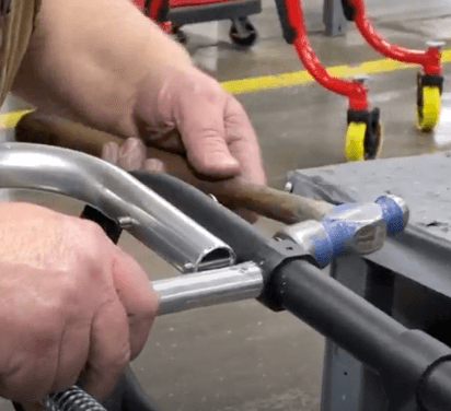
Insert the other end of the rod (no lock nut) into the corner hole of the main right frame.
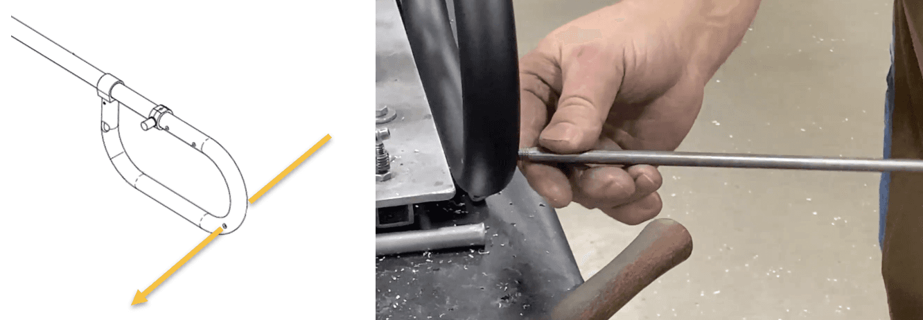
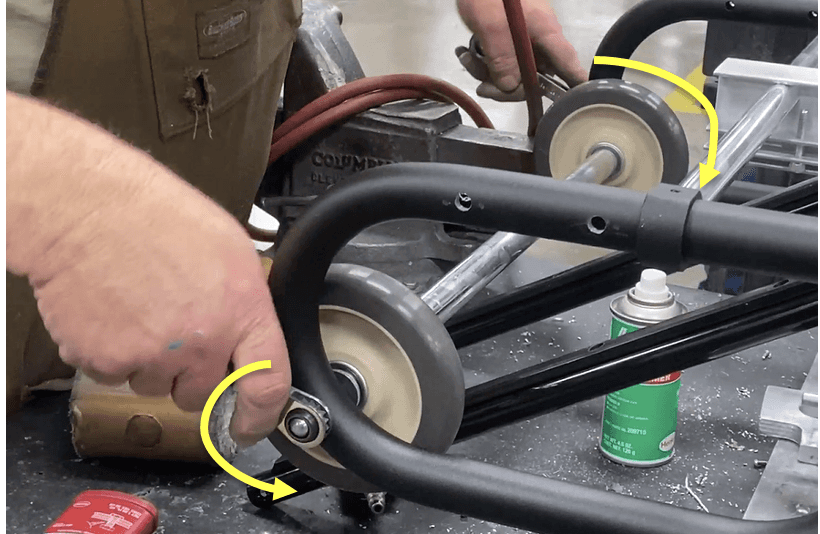
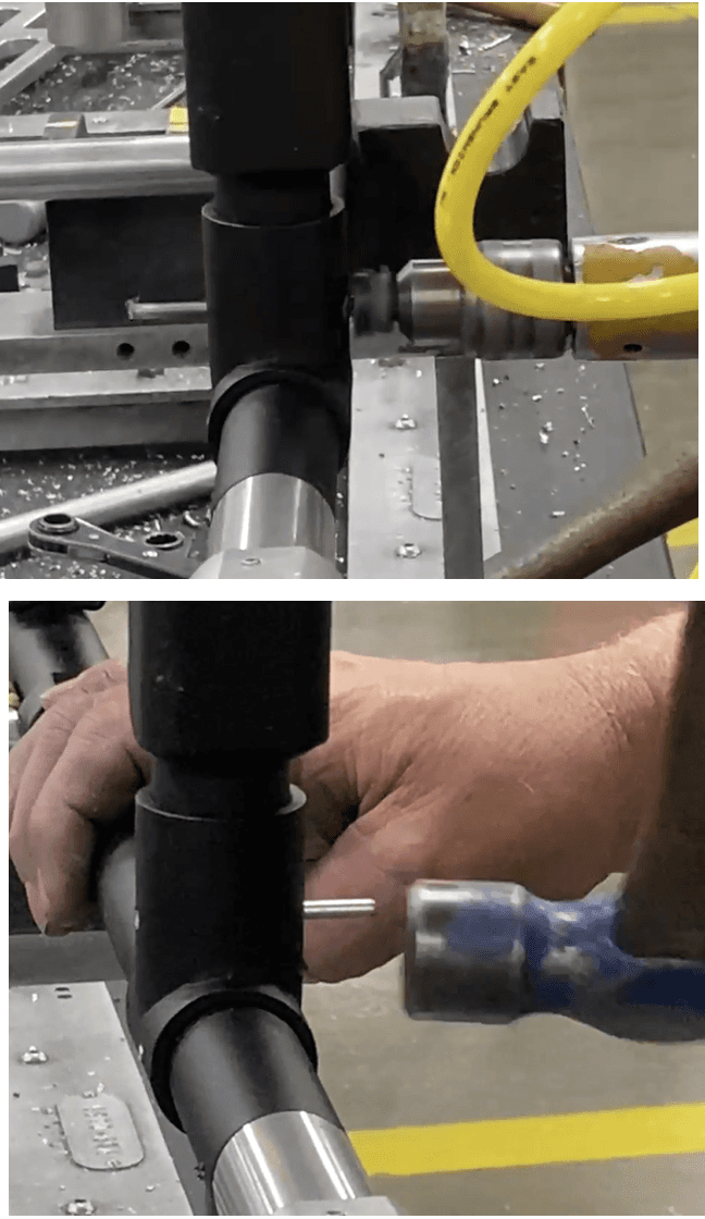
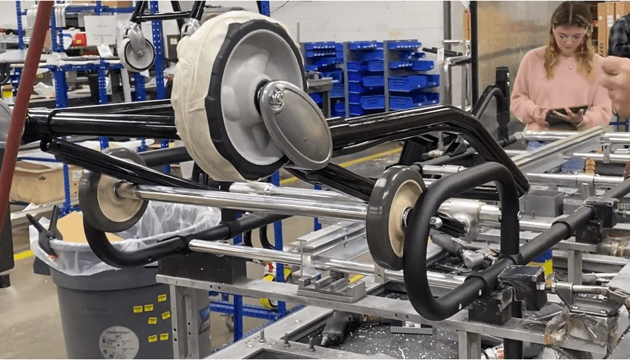
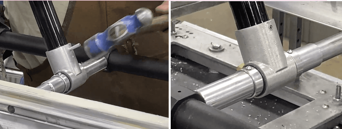
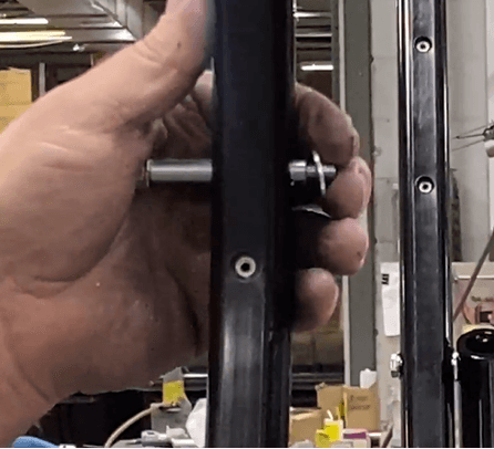
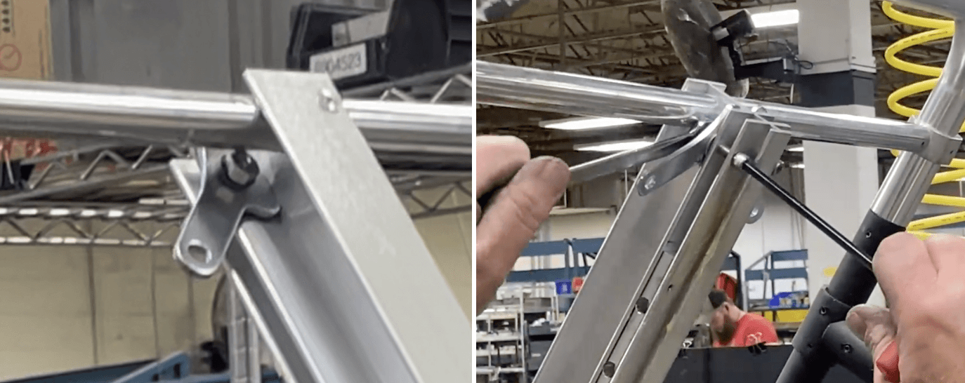
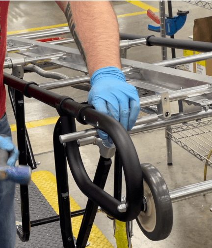
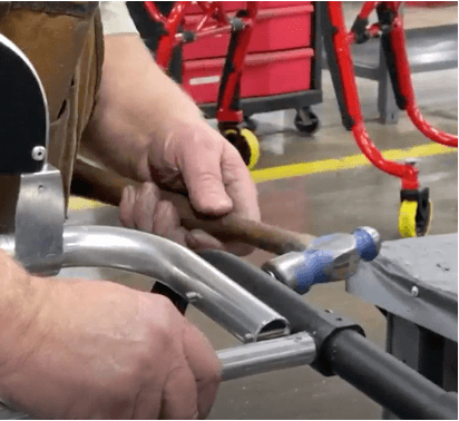
Once the rod is through both walls of the main right frame, at least past the rod’s thread, hammer (via mallet) in the rod through the main right frame’s corner hole. Hammer in until about 6 inches of the rod is through, as seen below.
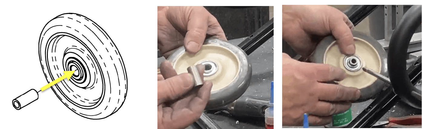
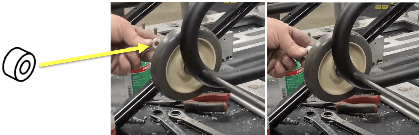
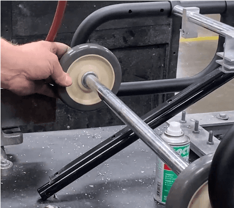
Get two 274-8001 (Wheel, 1.00 X 5.00 X .500 Bearing) and insert a 204-2742 (Bushing Load Wheel) into each wheel.
On the extruding rod, place a 3853550 (.326 X 1.000 X .120 FW ST TCZ (Washer)) followed by the wheel+bushing assembly.
Place an 8120570 (Axle Spacer) on the extruding rod, beside the wheel.
Place an 8192472 (Load Wheel Spacer) over the remaining extruding screw and the axle spacer, so the end of the load wheel spacer is against the wheel.
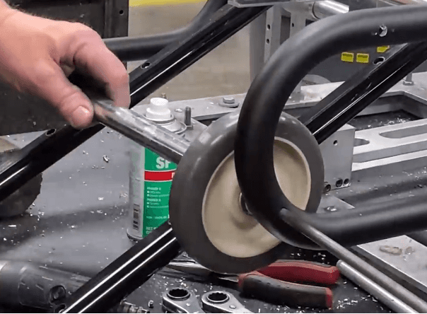
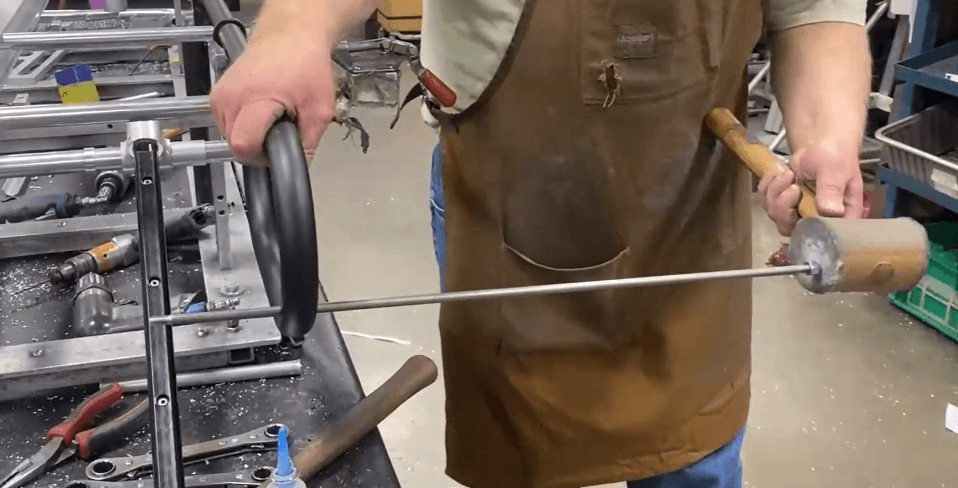
Hammer the rest of the axle rod through from the lock nut end.
a. It should now go through the wheel+bushing, axle spacer, and the load wheel spacer.
b. Hammer through the rod until ~4 inches are sticking outward from the main right frame. The other end of the rod should NOT be extruding from opening of the load wheel spacer.
The rod should be far enough through the load wheel spacer that the end of the rod is close to the opening of the spacer, BUT NOT past the opening.
Place a second 8120570 (Axle Spacer) onto the axle rod. Due to the location of the axle rod with the load wheel spacer, you must stick the axle spacer inside the load wheel spacer and onto the axle rod.
Install the second wheel+bushing onto the load wheel spacer (with the axle rod and axle spacer inside it). The opening face of the load wheel spacer should sit snug with circular divot on the wheel face.
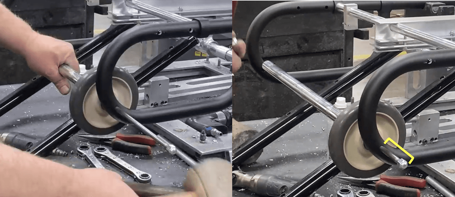
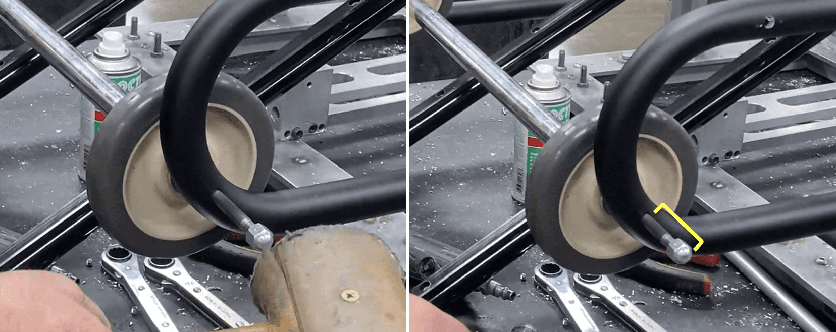
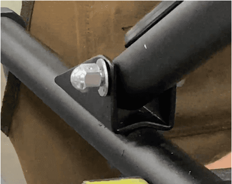
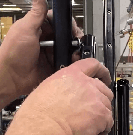
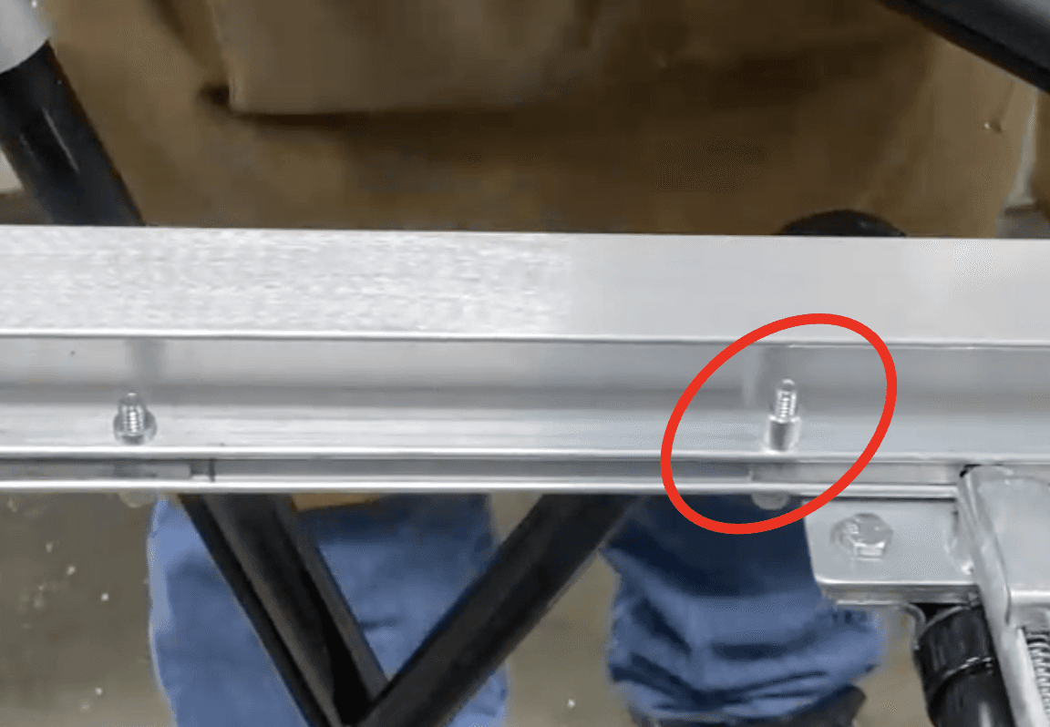
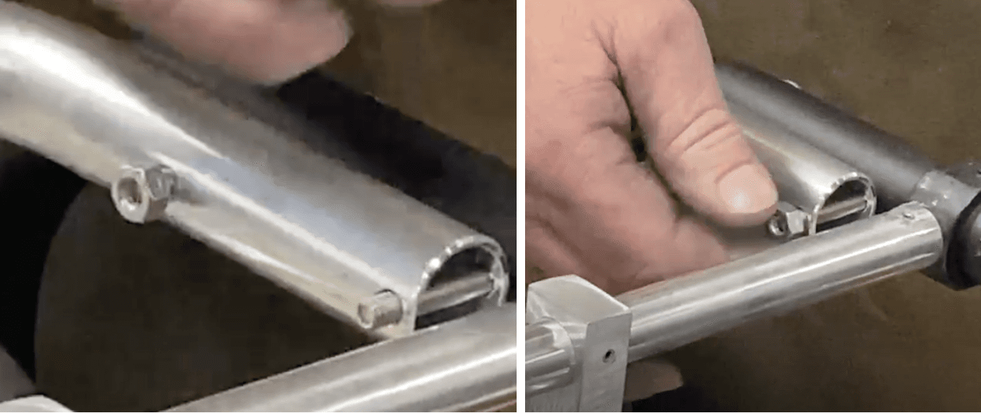
Hammer in the lock nut end of the rod again until ~2 inches are remaining (pictured below).
a. On the other end of the rod, it should be extruding about ~1 cm past the wheel+bushing.
b. DO NOT let it go through the main left frame.
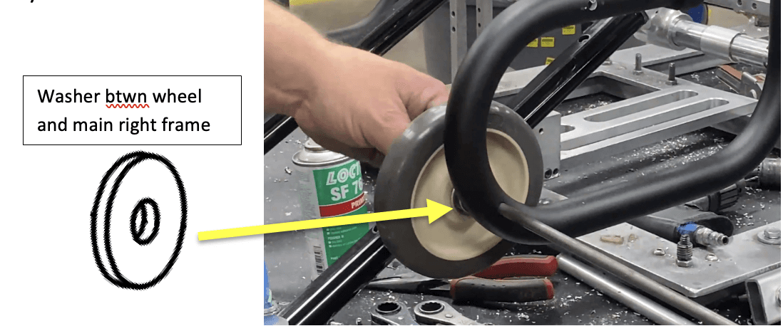
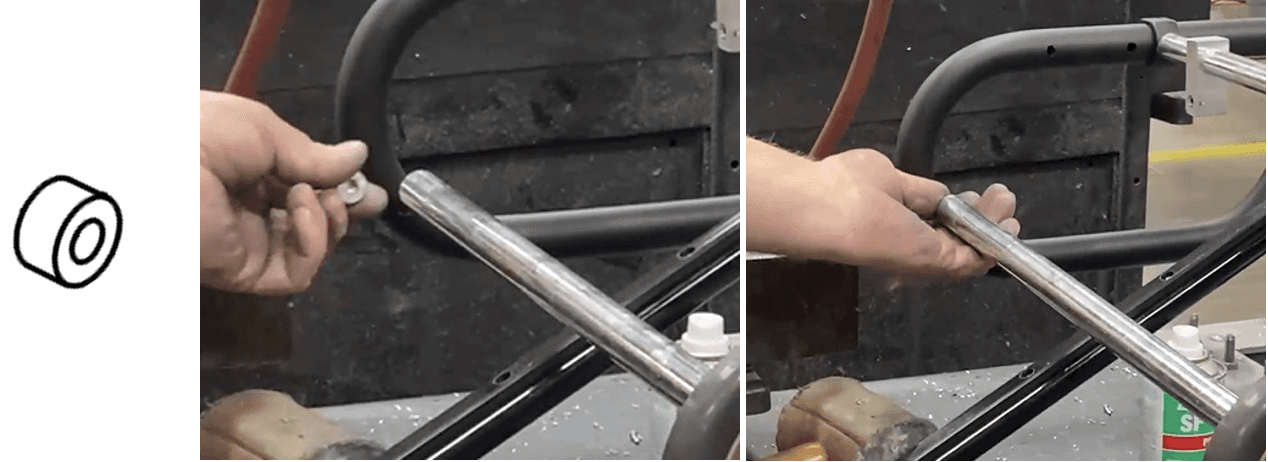
Place a 3853550 (.326 X 1.000 X .120 FW ST TCZ (Washer) on the end of the rod.
a. To help with access, gently pull out the axle assembly so the end is not hindered by the main left frame.
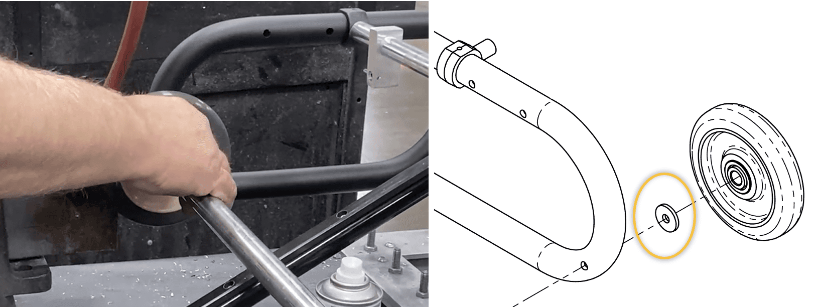
Align the remaining axle rod with the hole on the main LEFT frame. (The washer should be in between the wheel and the frame).
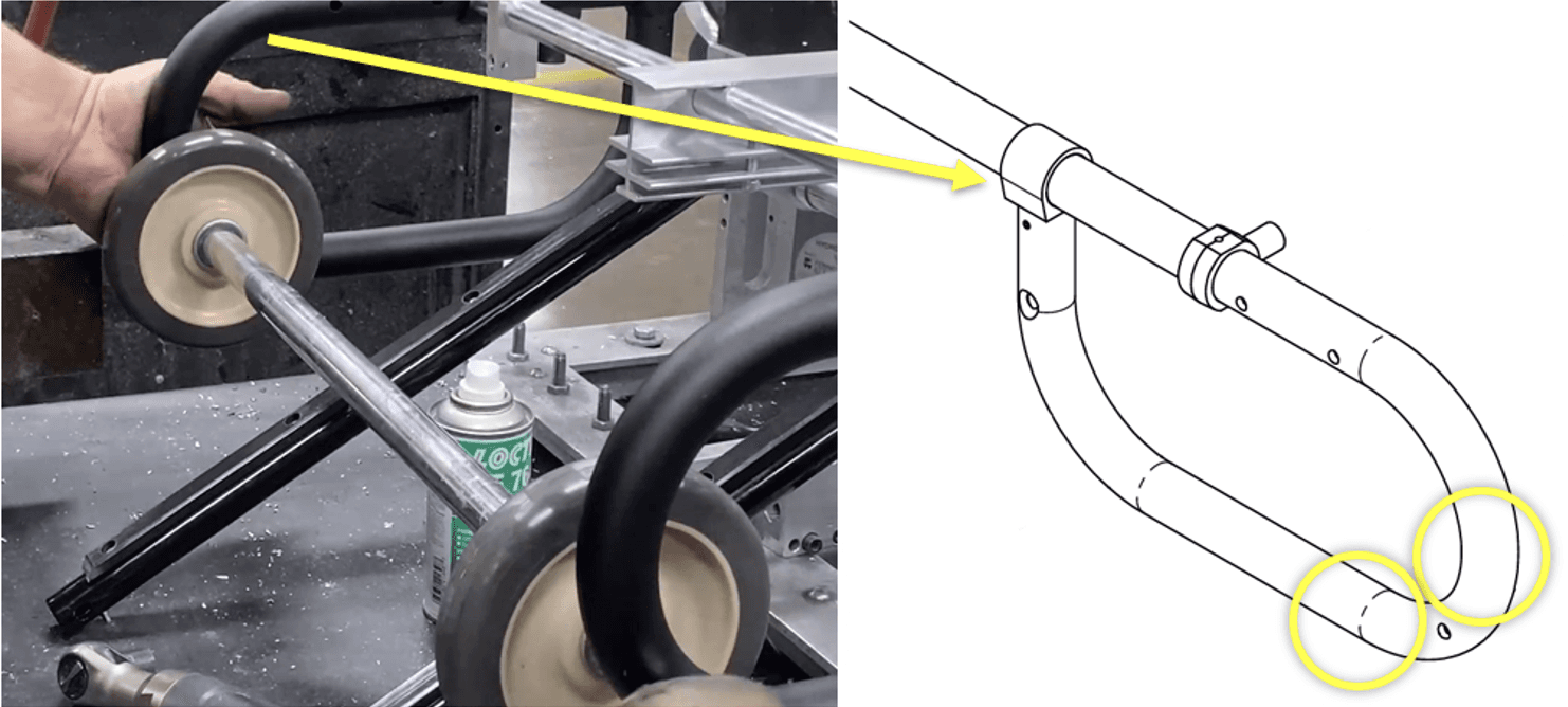
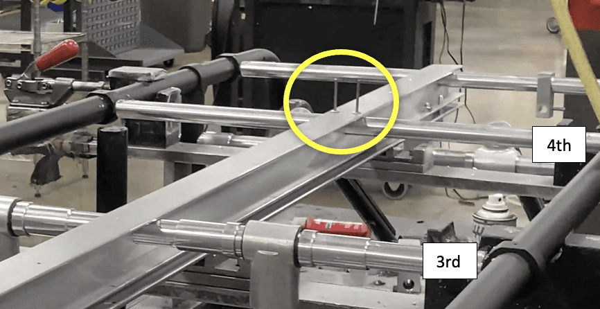
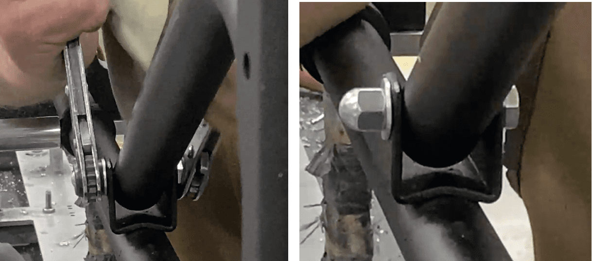
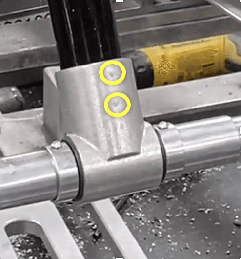
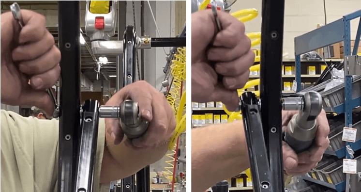
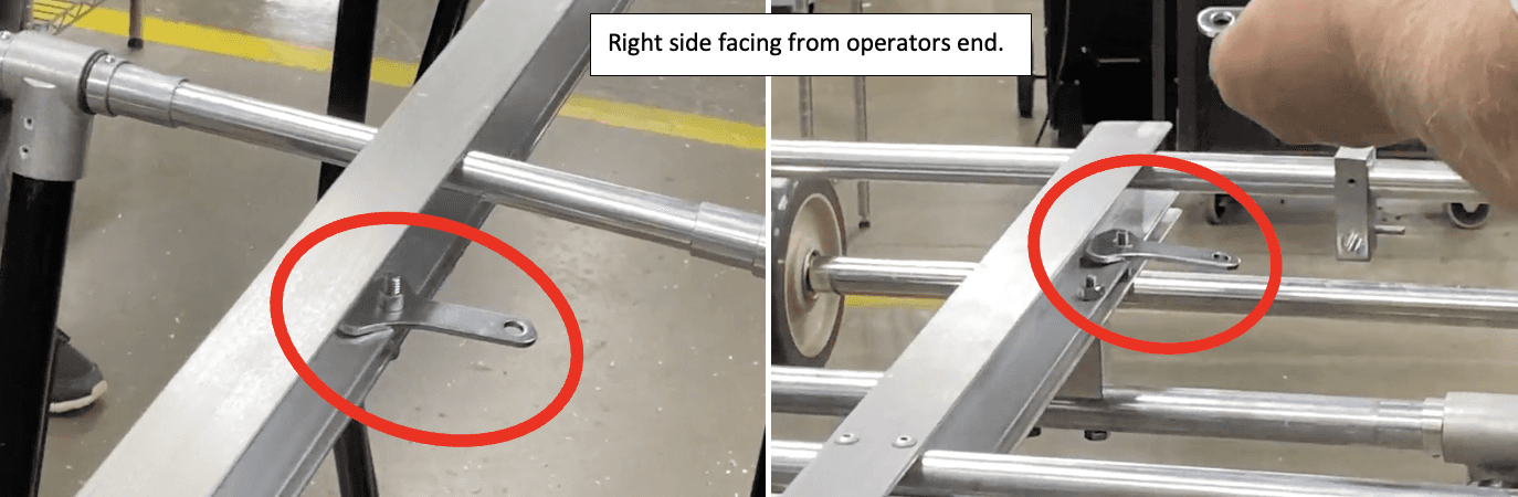
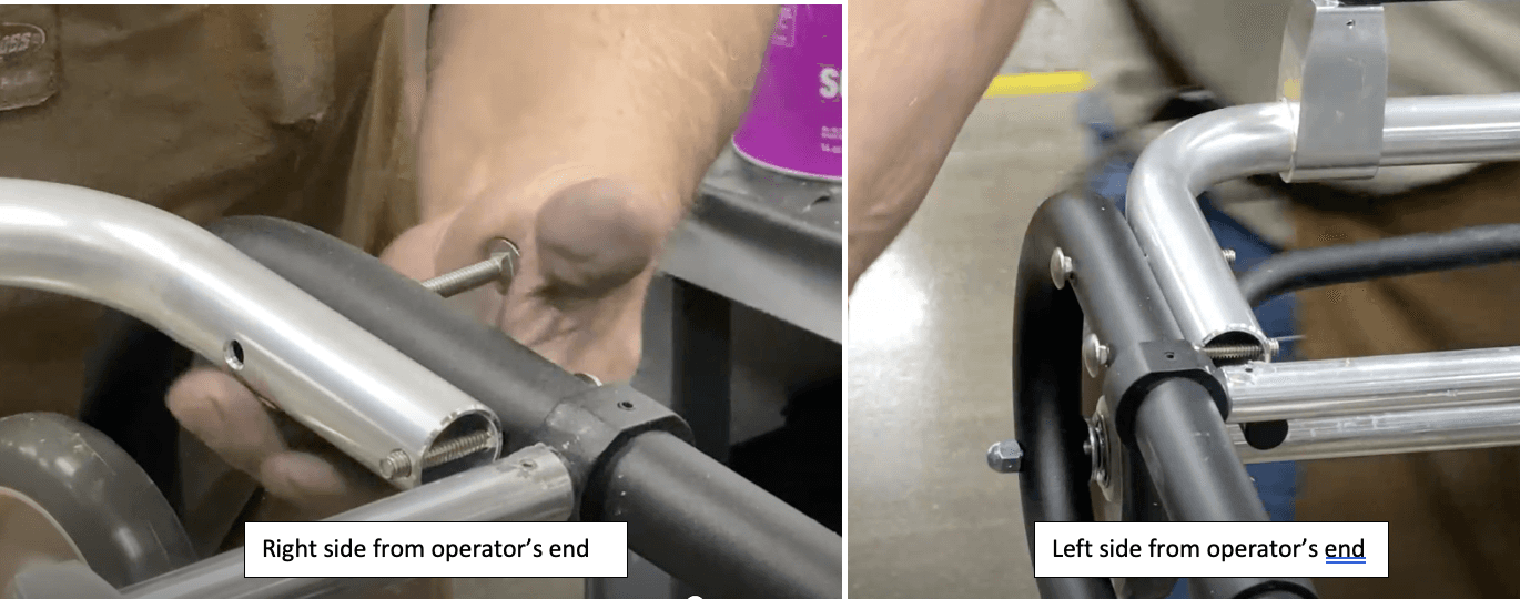
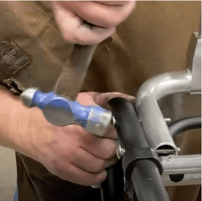
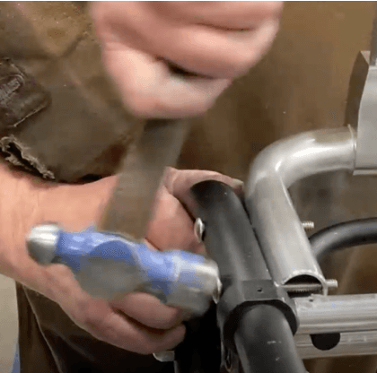
Hammer the lock nut end so the remaining axle rod goes through the hole, both walls, on the main left frame.
a. While hammering the lock nut end, use the palm of your hand to brace the left side so the rod can fully go through the main left frame. It should go through both walls of the frame.
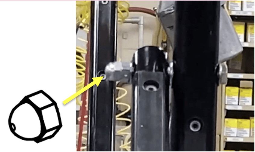
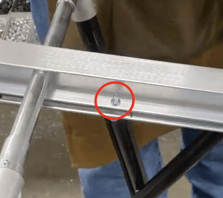
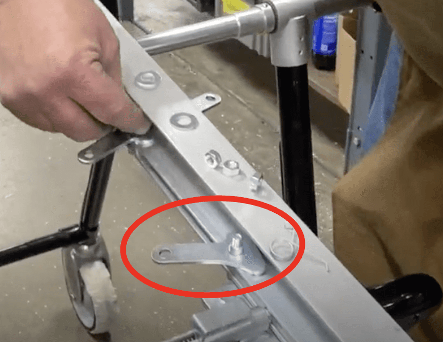
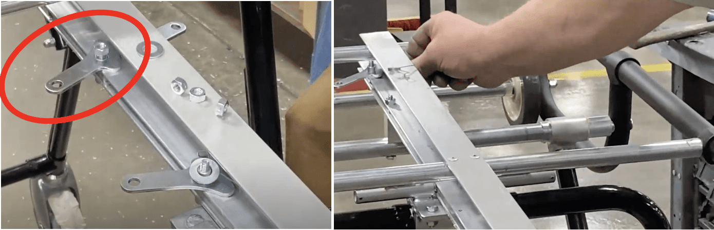
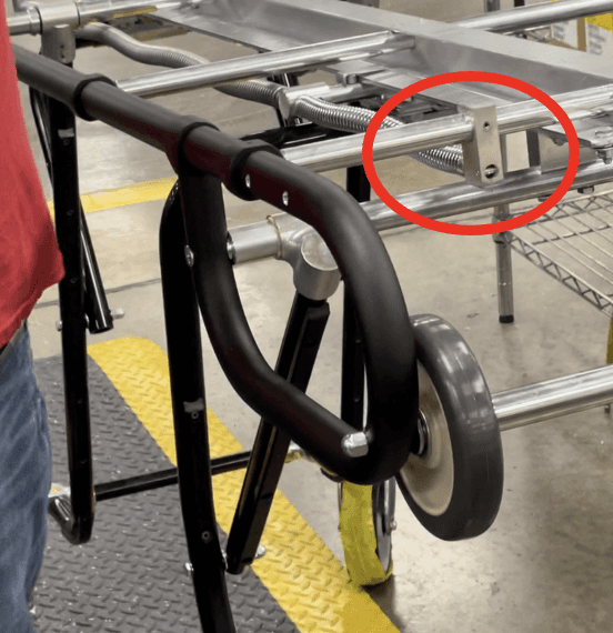
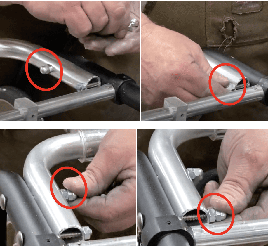
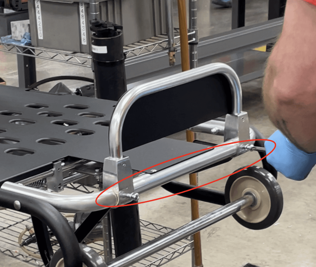
b. Switch sides: brace the right frame while hammering the left frame. Since there is no lock nut, hammer right by the hole the axle rod is going through, such as right above or below it (circled below).
Install a 330-6375 (.313-18 Acorn Lock Nut (Zinc)) onto the remaining threaded tip of the axle rod.
a. IF this acorn lock nut does NOT have the locking mechanism (interior elastic), USE blue 242 loctite.

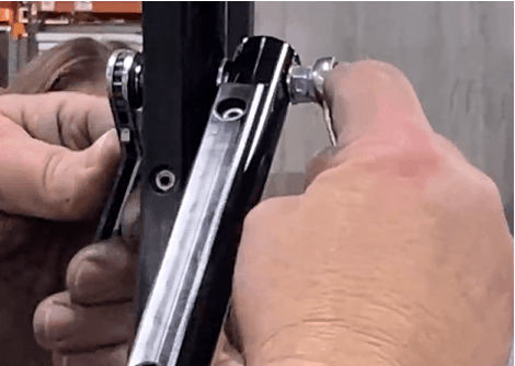
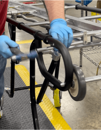
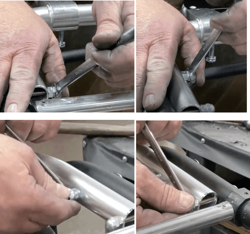
Use two ratchet combination wrenches (.313 diam) to tighten both lock nuts around both main frames.
Insert two 818-7620 (.750 X .584 X 6.000 Stiffener Tube) into the two openings of the 8192467 (Operator End Frame, miniMAXX). Insert the stiffener tubes as far as they can go. There will be about ~2-3 inches still sticking out on both ends.
a. Set this to the side to be used in step 40.
Install two 506-5190 (Casting – Bed Straight) into the two opening ends of the remaining 819-2486 (.75OD X .58ID X 19.745L Crosstube/X-tube) on the I-bar.
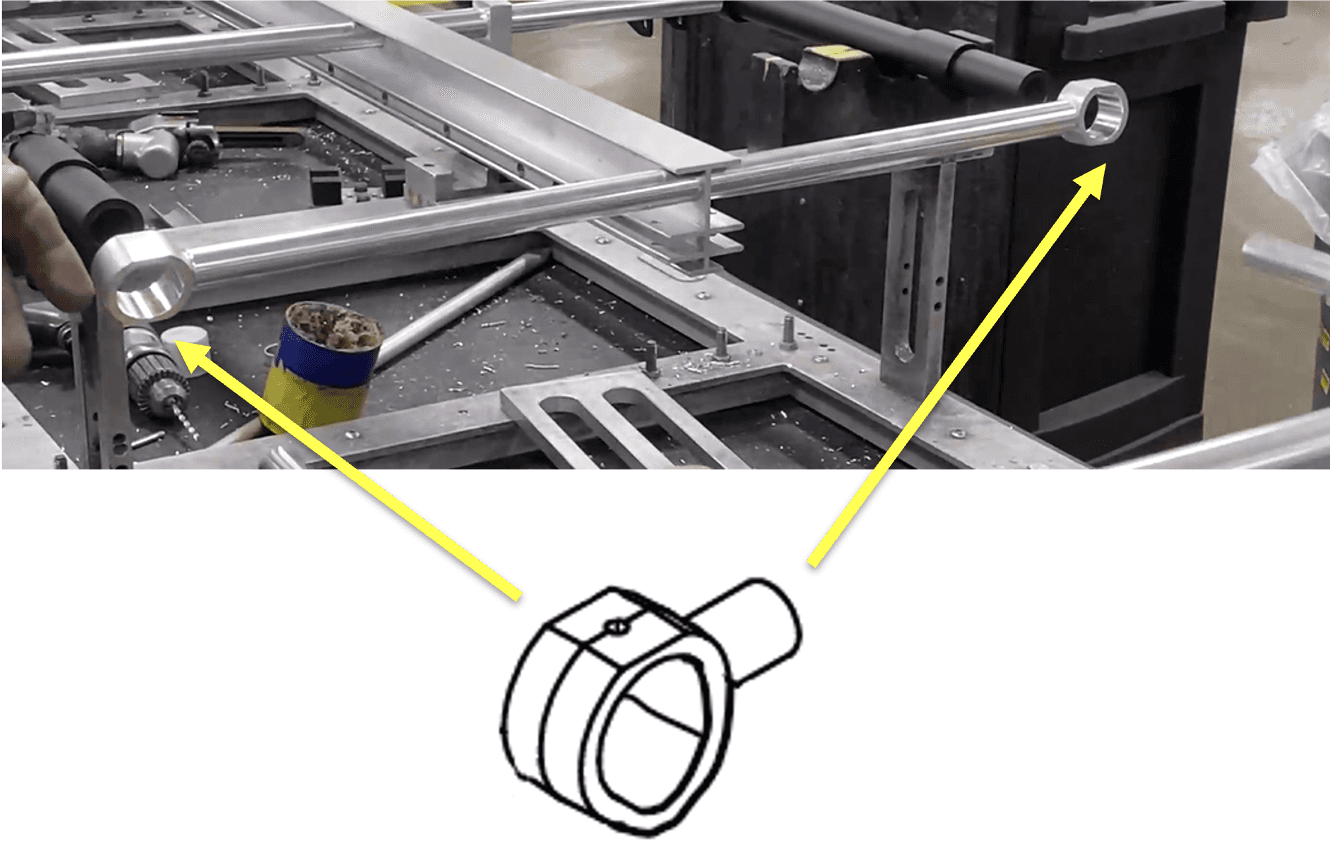
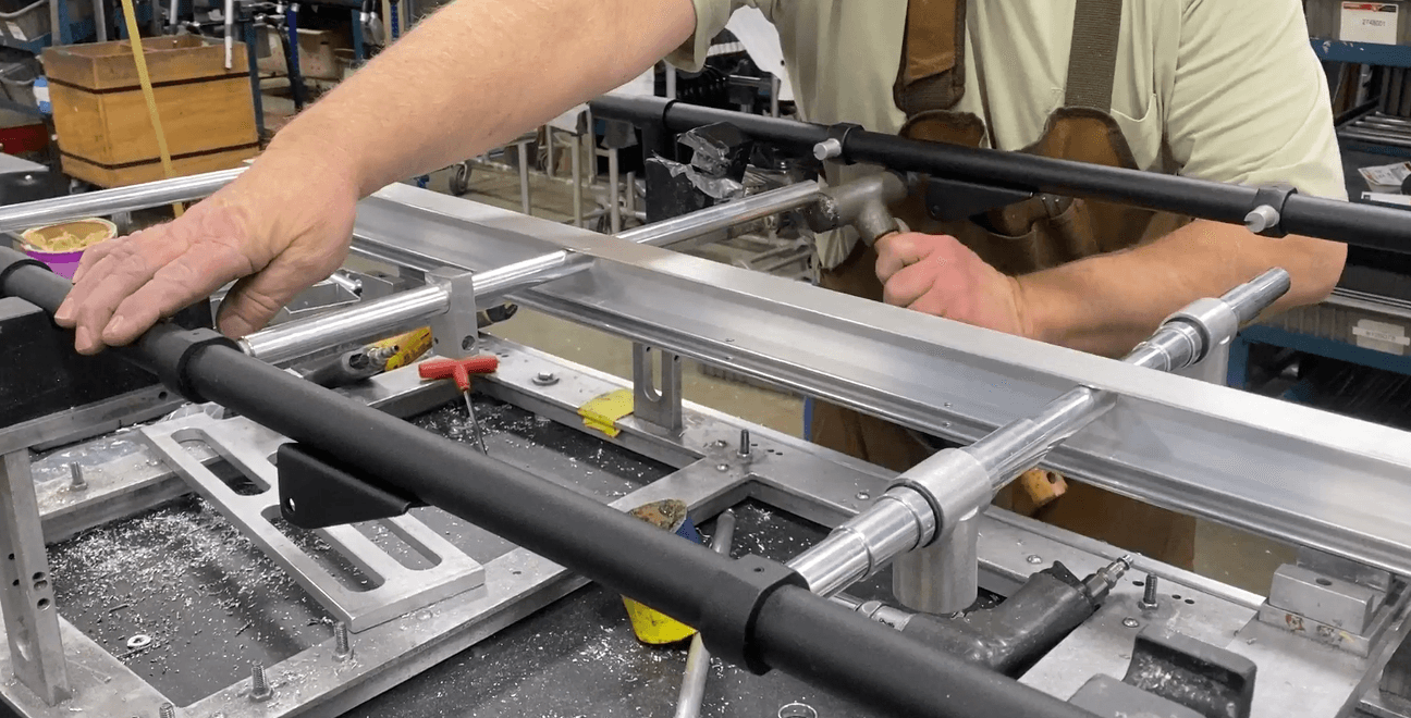
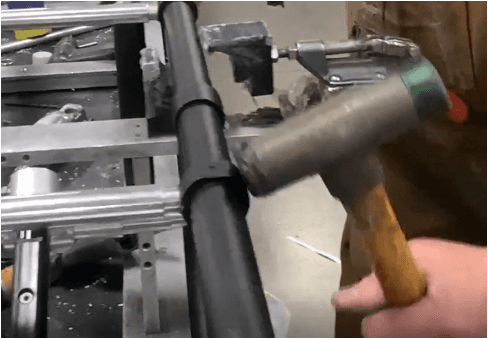
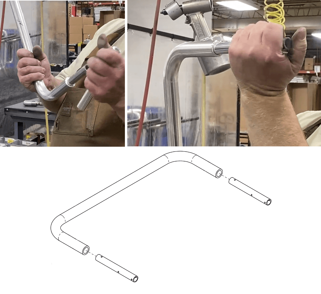
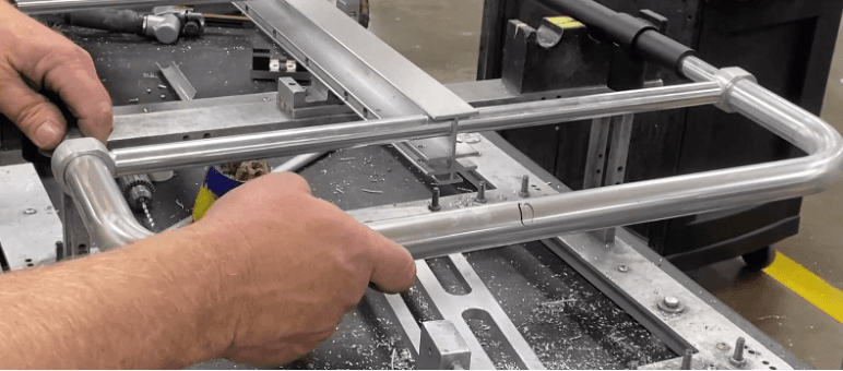
Insert the operator end frame+stiffenser tubes into the two castings and main frame openings. Hammer the operator end frame to fully secure it into the holes.
a. Also hammer the two castings+crosstube as needed so the crosstube is parallel with the operator end frame.

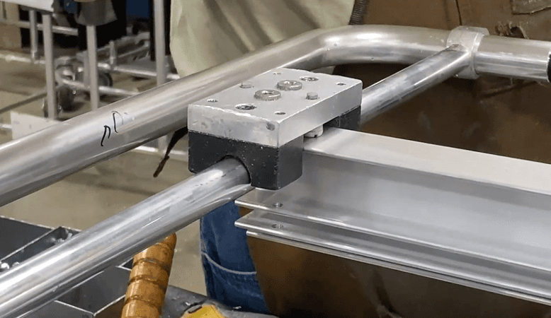
Place fixture 9300037 (Fixture, mainframe duplicate) on top of the crosstubes; the extruding cylinders should go around all 5 tubes, as seen below.
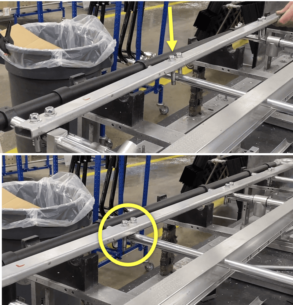
Use a marking pin and hammer to mark where to drill:
a. The side of the main frame ~1cm away from its intersection with the operator end frame.
b. The side of the 151-4590 (1.094 X 1.094 Weldment Tee) on the main frames (2 marks, 1 each side)
Mark on the side closest to the operator end.
c. The center of the top face of the castings (10 marks, 5 each side).
d. The ends of the crosstubes, ~1cm close to the attached bed straight castings/main frame (10 marks, 5 each side).
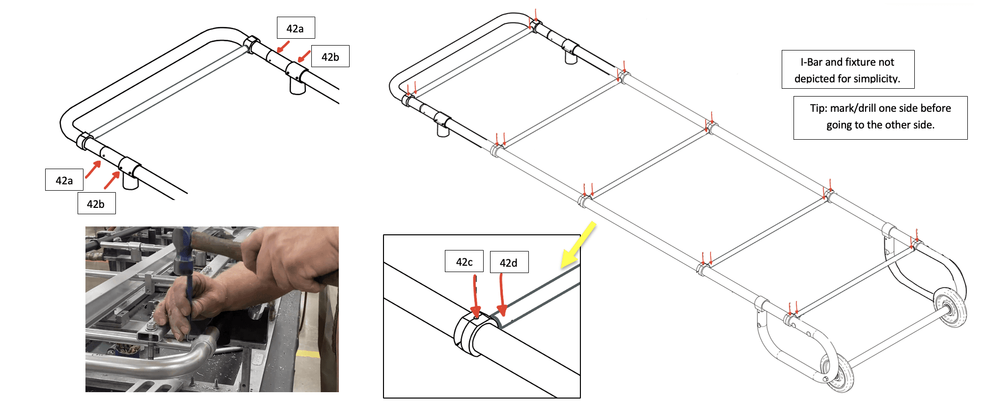
Drill with a .152 drill bit into all of the marked holes from 42a. Apply drill grease before drilling. Drill through all walls.
a. Hammer in a 345-2400 (.156 X 1.094 Roll Pin) into the 42a holes until the roll pin is flush with the frame.
Drill with a .152 drill bit into all the marked holes from 42b and 42c. Drill through all walls.
a. Hammer in a 3452800 (.156 X .375 Roll Pin) into the 42b and 42c holes until the roll pin is flush with the surfaces.
Drill with a .152 drill bit into all the marked holes from 42d. Then drill a second time with a .156 drill bit. Drill through all walls.
a. Hammer in a 345-1800 (.156 X .750 Roll Pin) into the 42d holes until the roll pin is flush with the surfaces.
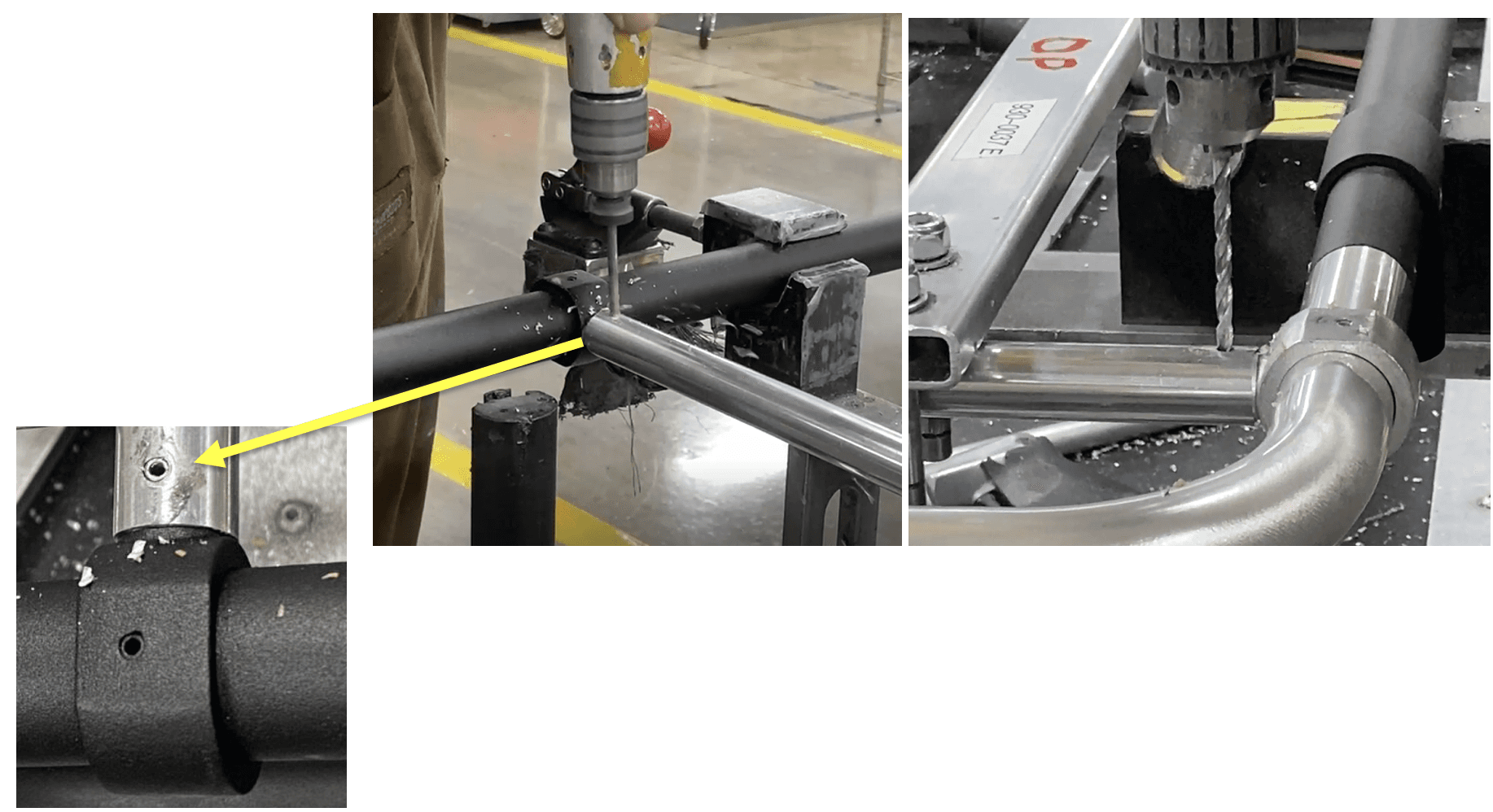
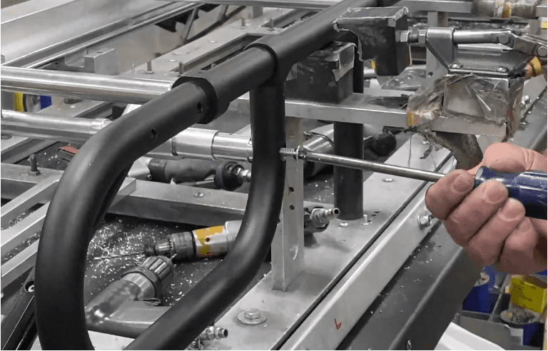
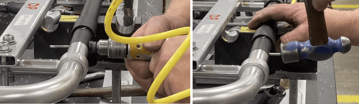
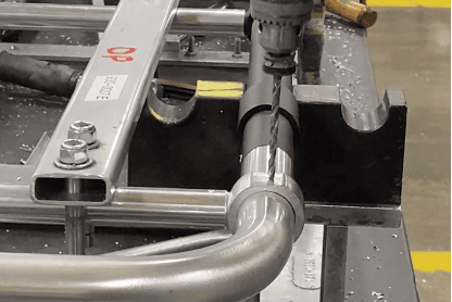
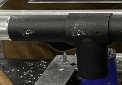
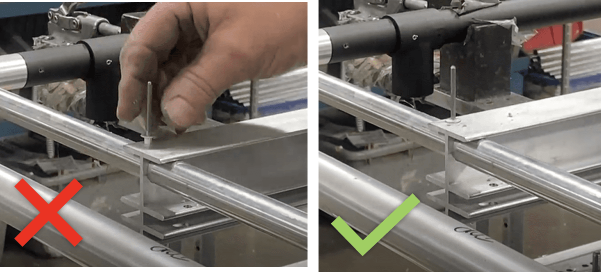
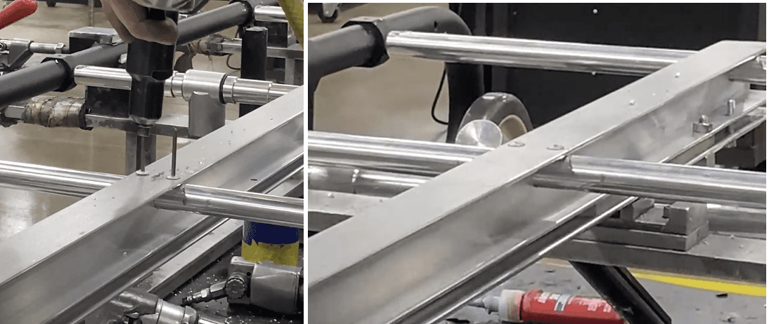
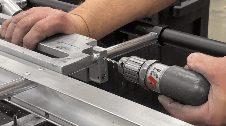
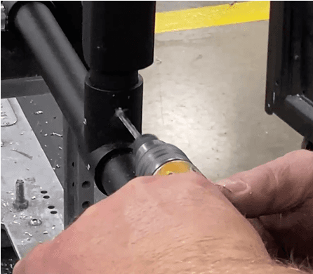
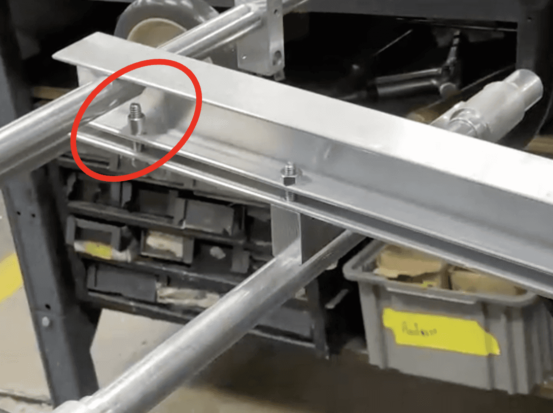
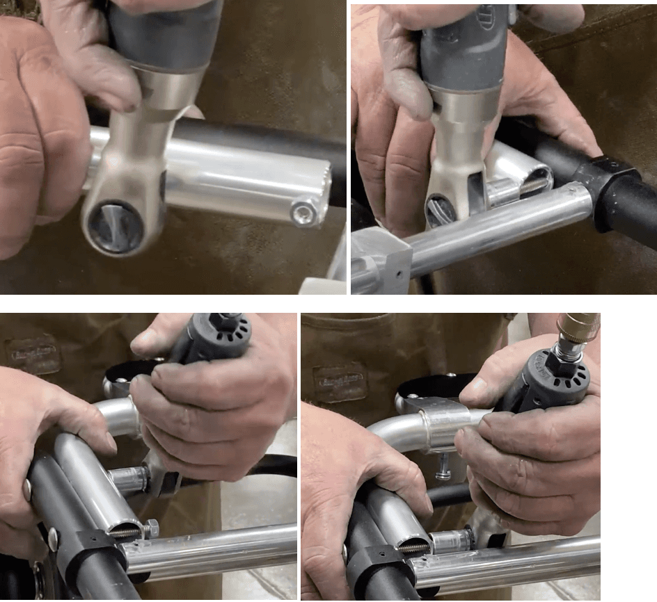
Place fixture 9310459 (Fixture, Drill I-Beam) on the operator end of the I-beam, as seen below.
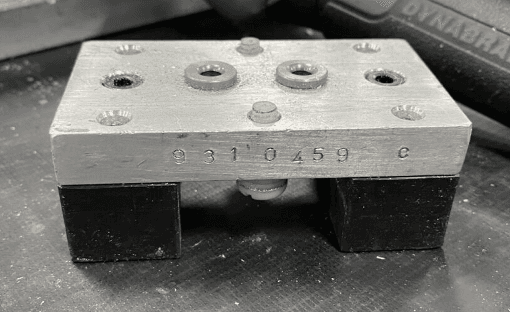
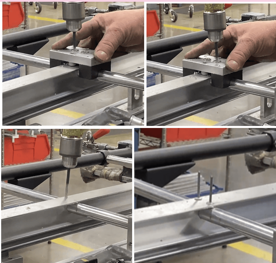
Drill with a .192 drill bit into the right-side hole on the fixture (refer to picture for orientation aid). Drill through ONE wall only.
a. Use the fixture to drill through the I-beam. Then take the fixture off and drill cautiously to go through ONE wall.
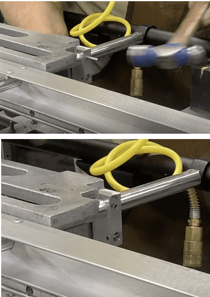
b. You can use a 340-2100 (AD-66-AD Pop Rivet .187) to test the depth of the hole.
Drill until the pop ricket sits flush with the I-beam. Keep the pop rivet placed in the hole.

Place the same fixture 9310459 on the next cross beam.
Repeat step 47 for both holes: Drill (.192 drill bit) through I-beam, remove fixture, drill until pop-rivet (340-2100) is flush.
Repeat steps 48 and 49 for the 4th crosstube away from the operator end (not the next crosstube, but the one after).
Use a pop rivet gun to secure all 5 rivets into the I-beam/cross tube holes.
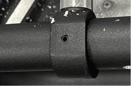
Place fixture 9310375 (OP-END Fixture, Assy 24) on the left side of the I-beam, on top of the 2nd and 3rd crosstube away from the operator end frame. It should sit against the I-beam. The indented corner of the fixture should face the operator end frame/the 2nd crosstube.
Move the spring rod hanger (8093620) on the 2nd crosstube so it is against the first indent of the fixture.
Drill with a .156 drill bit into the spring rod hanger where it intersects with the 2nd crosstube. Drill through all walls. 55. Hammer in a roll pin .156 X ___ until it is flush with the block surface.
Place fixture 9310375 (LOAD-END Fixture, Assy 24) on the left side of the I-beam, on top of the 4th and 5th crosstube away from the operator end frame. It should sit against the I-beam. The indented corner of the fixture should face the wheels/the 5th crosstube.
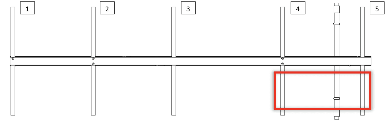
Repeat steps 53-55 with this second spring rod hanger on the 5th crosstube (move hanger -> drill -> roll pin).
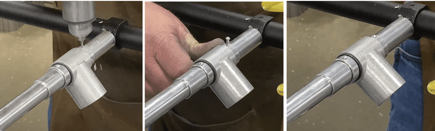
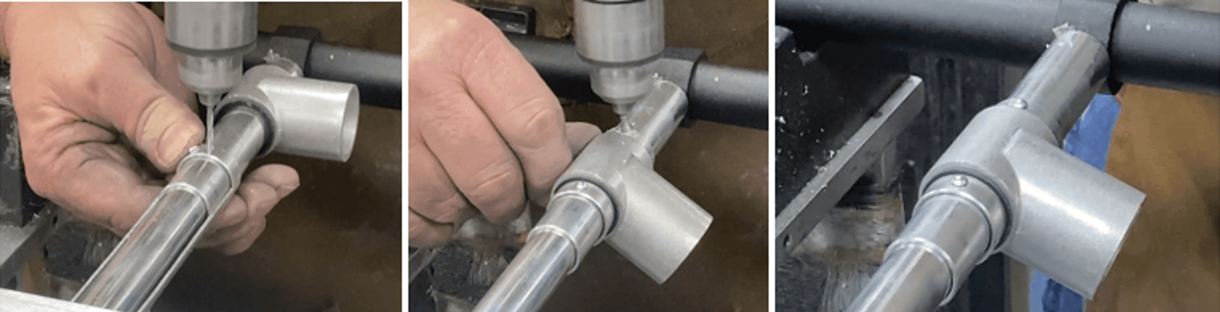
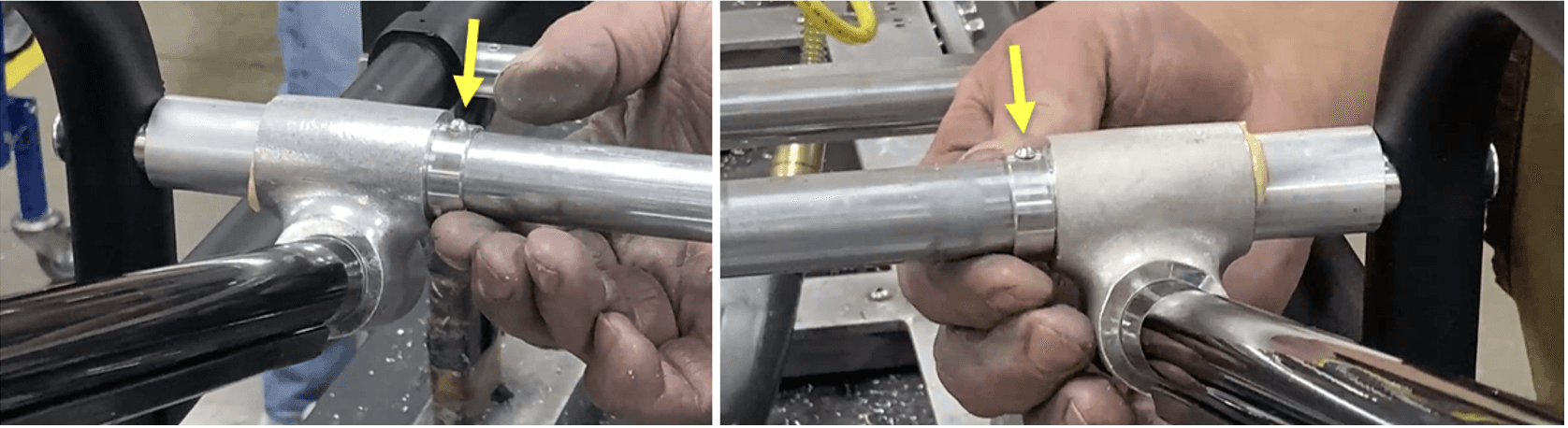
On the 3rd crosstube right side, move the 819-2098 (Sleeve), 152-2615 (Weldment-Tee), and the two 818-6980 (Ring Spacers) sets away from the I-beam. The spacer should be as far as possible, against the main right frame, with the weldment-tee and ring spacers on it.
On one side, place the half-cylindrical spacer (fixture type) against the I-beam and hugging the 3rd crosstube.
Move the closest ring spacer against the half-cyl. spacer.
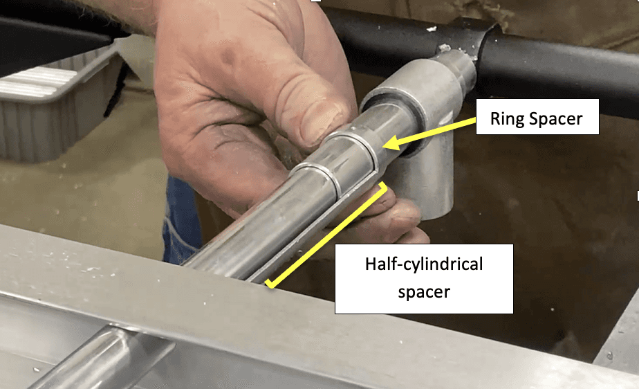
Rotate the ring spacer to locate one hole on it. Center the hole on top of the crosstube.
a. Keep the ring spacer against the half-cyl. spacer!
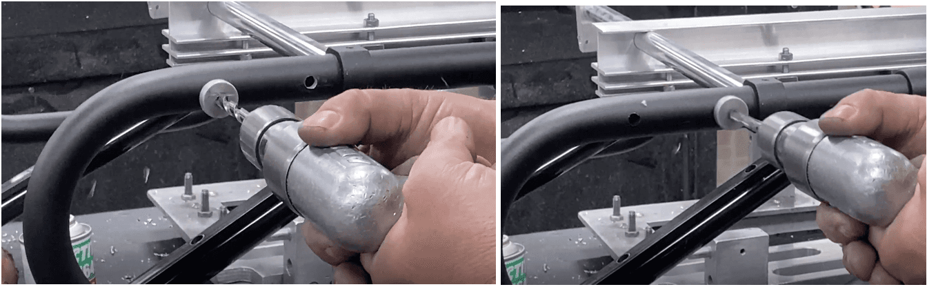
Drill with a .104/#37 drill bit through the hole onto the crosstube. Drill through one wall only.
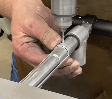
Insert and hammer in a 310-1200 (#4 X .375 Drive Screw-Type U) into the drilled hole.
a. Once the drive screw is secure enough that the ring spacer does not move, the half-cyl. spacer is not needed anymore.
Move the weldment-tee against the drilled-in ring spacer. Move the remaining ring spacer against the weldment-tee.
Repeat steps 61 through 63 (rotate -> drill (.104/#37 drill bit) ->drive screw (#4 X .375)).
Repeat steps 58 through 65 on the left side of the I-beam.
a. General steps: move set away from I-beam half-cyl. Spacer -> drill ring spacer -> move tee -> drill other ring spacer.
FLIP OVER the entire subassembly and place it back onto the fixture.
a. The main (right) frame should be in the second wrung of the fixture, where the main left frame was before.

Go to the load end leg subassembly.
a. Move the leg spacers outwards and towards their respective sides’ main frames.
b. Move the ring spacers inwards towards the I-beam.
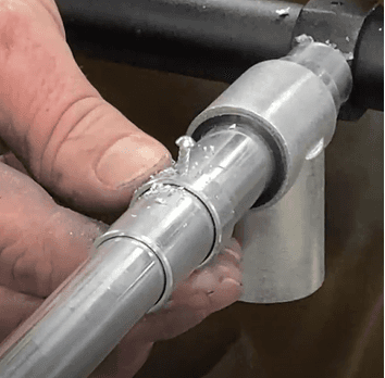
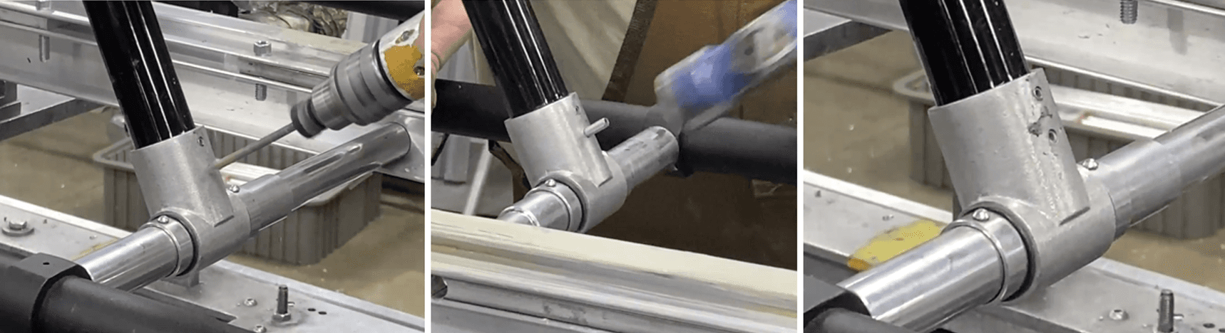
Paint grease next to the leg spacers, around the tube and about the width of the offset tees (506-1601).

Move one of the load end leg brace+offset tees over the greased spots; they should be flush and against the leg spacers.
Move the ring spacers against the offset tees.
a. It does NOT matter which side is done first.

Like step 61, rotate the ring spacer to locate one hole on it (one hole on each ring spacer).
a. Center the hole on top of the crosstube.
Drill with a .104/#37 drill bit through the hole onto the crosstube. Drill through one wall only. Do this for both sides.
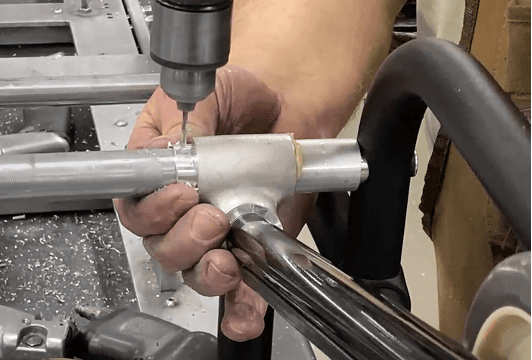
Insert and hammer in a 310-1200 (#4 X .375 Drive Screw-Type U) into the drilled holes.
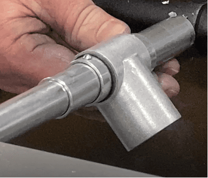
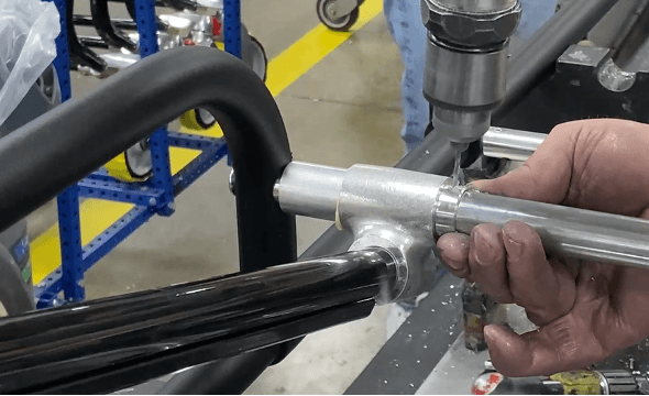
Go to the 3rd/middle crosstube.
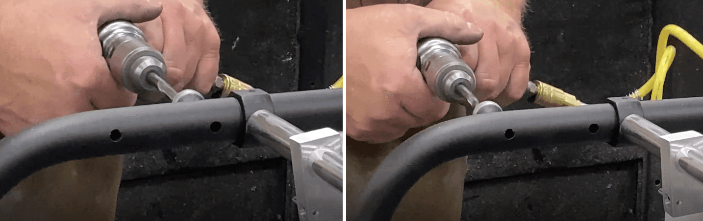
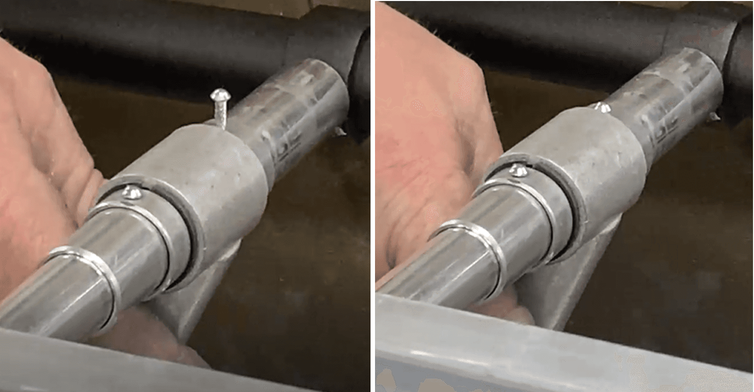
Drill with a .104/#37 drill bit the top face of all ring spacers (4 total, 2 each side of I-beam), centered on the crosstube.
a. Use drill grease on the drill bit before drilling on each side.
b. Drill through one wall only; you will feel the drill bit “slip” free inside the tube once it is drilled far enough.
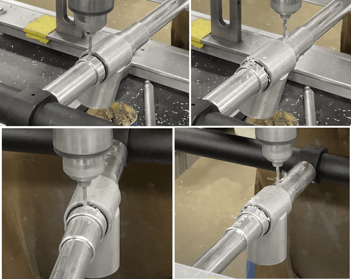
Insert and hammer in four 310-1200 (#4 X .375 Drive Screws) into each of the four drilled holes on the four ring spacers.
a. (Pictured below is just one side. Do this for both sides.)
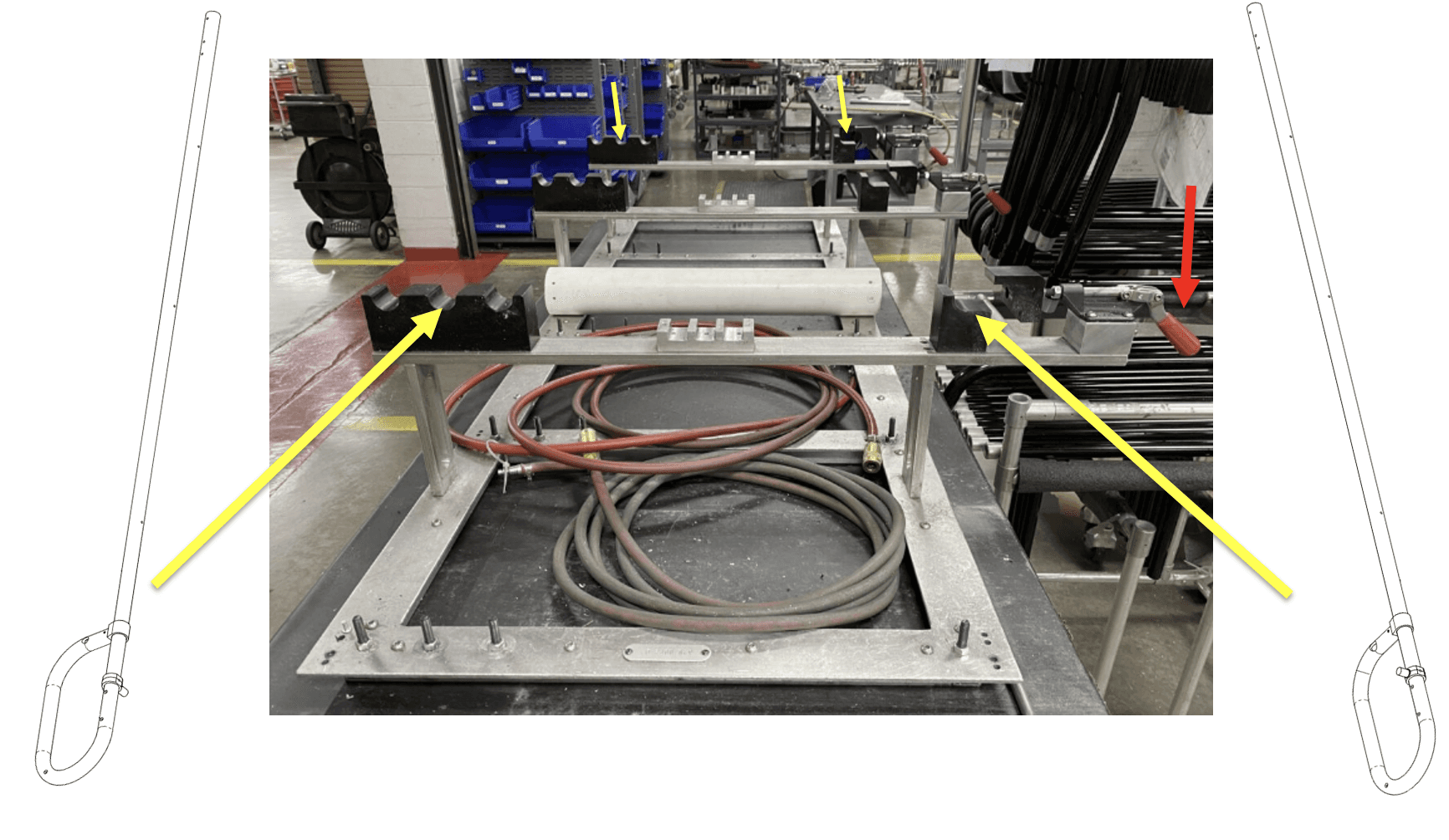
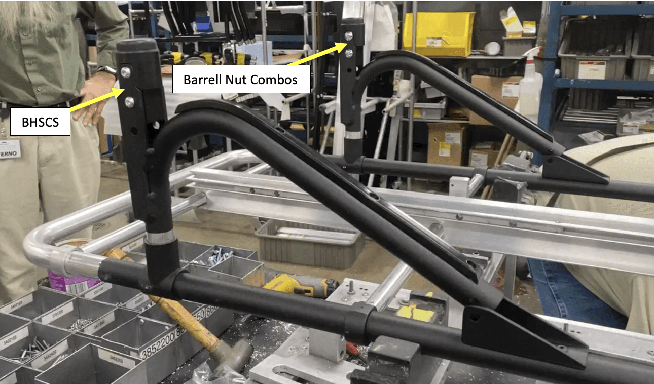
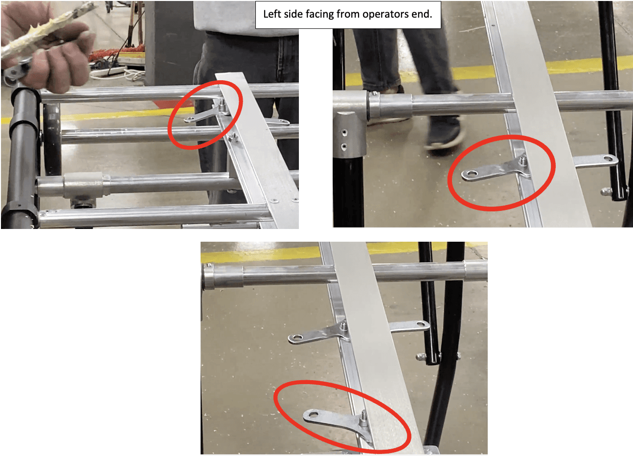
Get two post brackets (See “Post Bracket Subassembly” work instructions) and place them on the operator end as such:
a. Orientation guide, on each post bracket:
i. The two 365-3898 (.250-20 X .500 Button Head Socket Cap Screw (BHSCS) ZNC PC80) should face outboard.
ii. The two 390-3835 (Barrell Nut Combo .312 X 1.50 ZP) should face inboard.
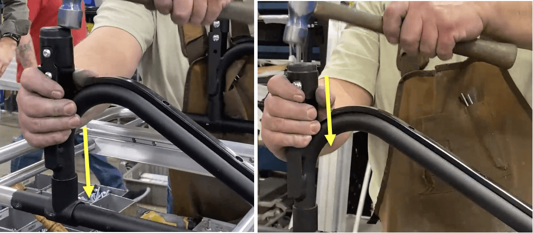
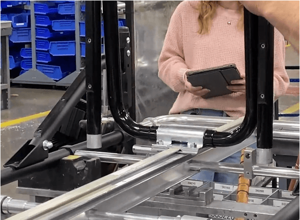
Use a mallet to hammer in the post brackets. Hit the rubber bumper.
a. Hammer until the post bracket column in fully in the 151-4590 (Weldment Tees 1.094 X 1.094).
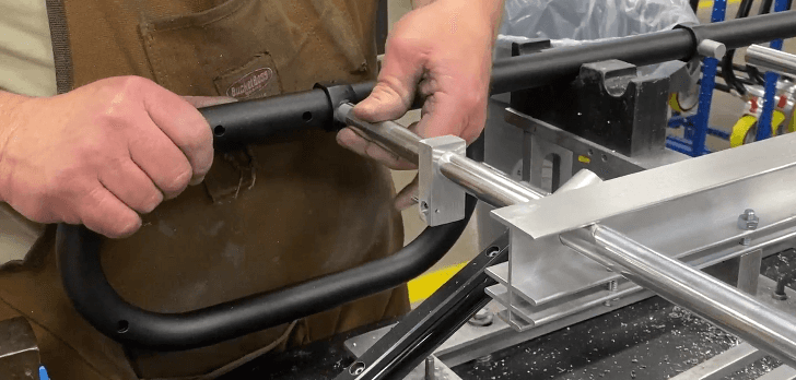
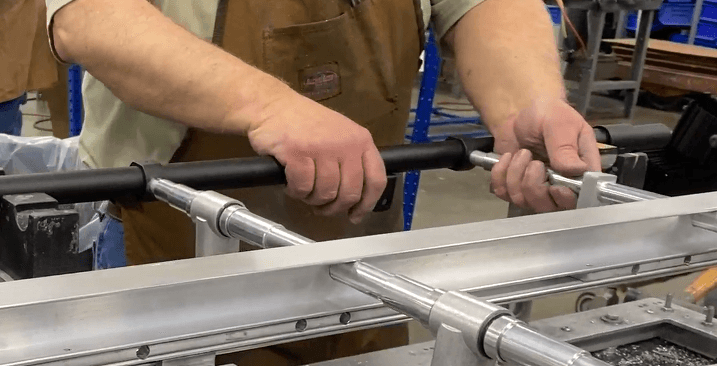
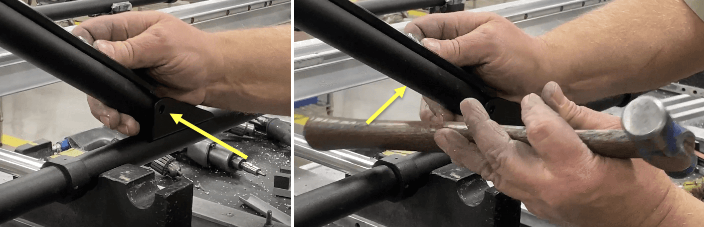
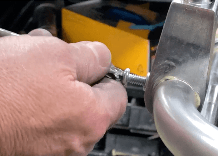
Maneuver the other end of the post support tube so the hole in it and the hole in the 815-9217 (Wheel Mount, S-Kit Brace) are aligned. Because of the tight fit between the wheel mount, use the hammer handle to help push the post support in place.
Install a 325-3100 (.313-18 X 1.7500 Hex Head Cap Screw (HHCS) ZP G5) into the aligned hole.
a. Optional: Put Loctite primer 7649 and blue 242 loctite on the threaded portion of the HHCS.
b. Hammer the HHCS in until at least the threaded side extrudes from the other side.
c. Use a ratchet combo wrench (.313” diam.) to install the HHCS further.
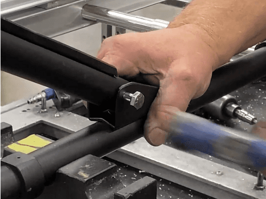
Place a 385-2300 (.750 X .313 X .063 Flat Washer .250 STD) and a 330-6375 (.313-18 Acorn Lock Nut (Zinc)) onto the thread.
Use two ratchet combo wrenches (.313” diam.) to tighten the acorn lock nut and HHCS around the wheel mount.
84. Repeat steps 80 through 83 for the other post bracket. (the HHCS should face outboard; mirror the other side).
Drill with a .152 drill bit through the center of the weldment tee and post bracket.
a. Eyeball its location: have it as centered as possible between the frame and the post bracket.
b. Drill in the direction towards the I-beam. Drill through all walls.
Hammer in a 3452800 (.156 X .375 Roll Pin) until it is flush with the surface.
Repeat steps 85 and 86 for the other post bracket / other frame.
Drill with a .152 drill bit 90 degrees away from the previous hole and centered on the weldment tee.
a. Eyeball its location: position this hole to be above the previous hole (so the roll pins do not intersect.)
b. Drill in the direction parallel to the I-beam / main frame. Drill through all walls.
Hammer in a 3452800 (.156 X .375 Roll Pin) until it is flush with the surface.
Repeat steps 88 and 89 for the other post bracket / other frame.
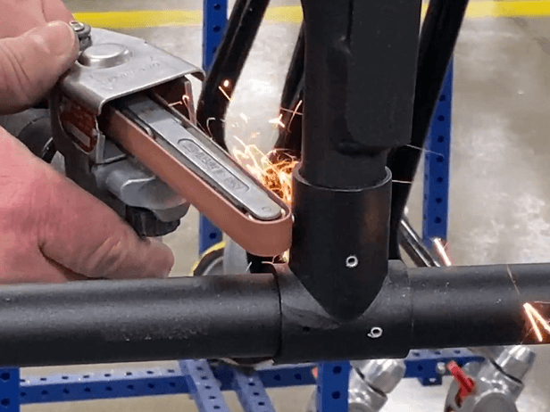
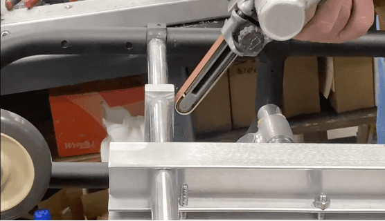
Sand down any roll pin surfaces with a powered belt sander.
Touch up the roll pin surfaces that are on black surfaces with black paint.
Touch up the roll pin surfaces that are on black surfaces with black paint.
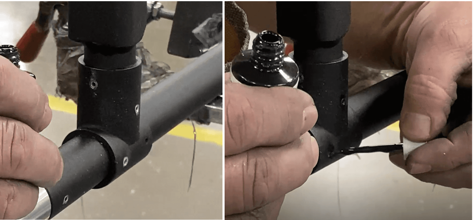
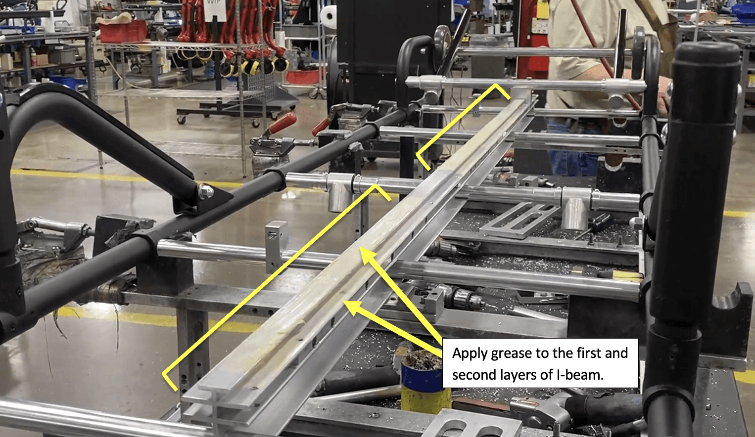
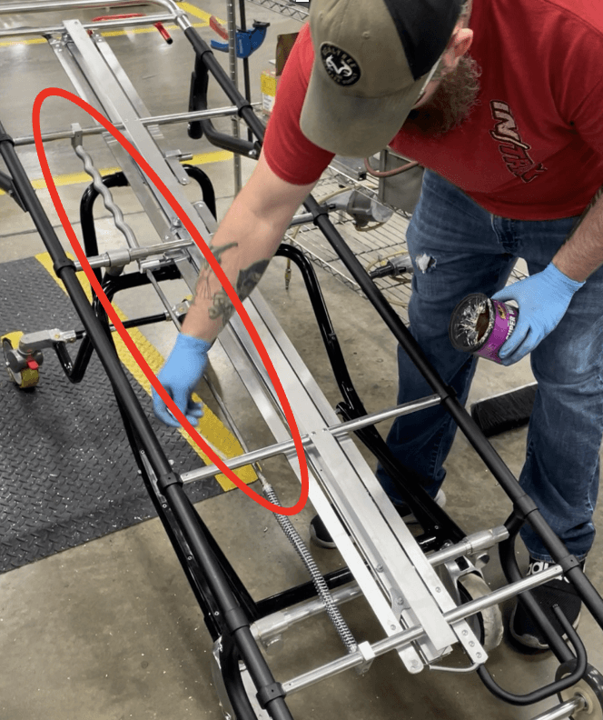
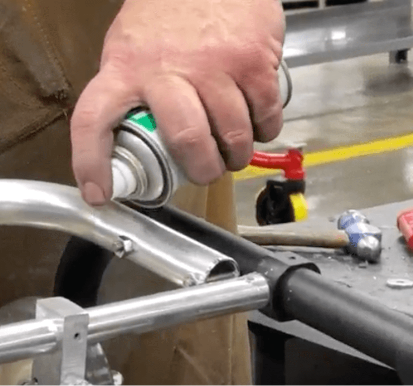
Apply grease on the two top layers of the I-beam.
a. Paint from the 3rd crosstube to the load end.
b. Paint again from the operator end of the I-beam to between the 2nd and 3rd crosstube (from the operator end).
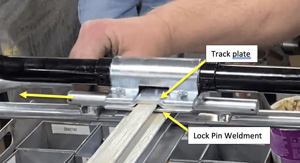
Slide the Load End Leg Frame (See “Load End Leg Frame Subassembly” Work instructions) from the operator end of the I-beam. Slide the I-beam through the space between the track plate and the lock pin weldments.
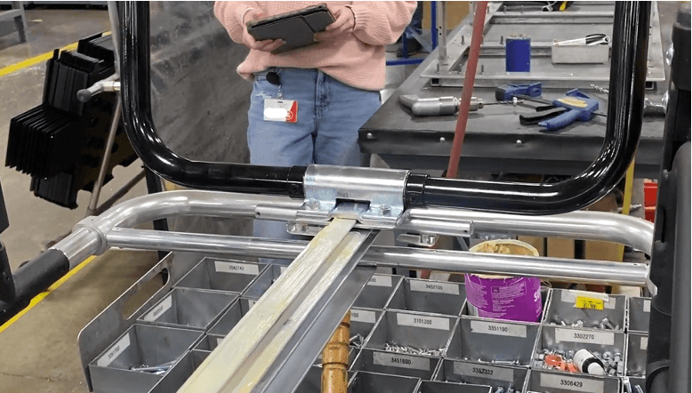
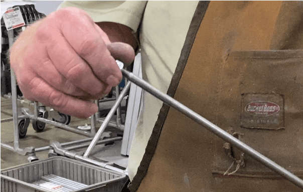
Use a pole/piston to pull out the 1508790 (Lock Welded Pin) so the Load End Leg Frame can slide to the other side.
Slide the Load End Leg Frame towards the load end.
a. Position the lock pin weldment portion of the load end leg frame so that it is by the 2nd crosstube from the load end/4th crosstube from the operator end.
97. Rest the frame on the load end leg braces (8192086).
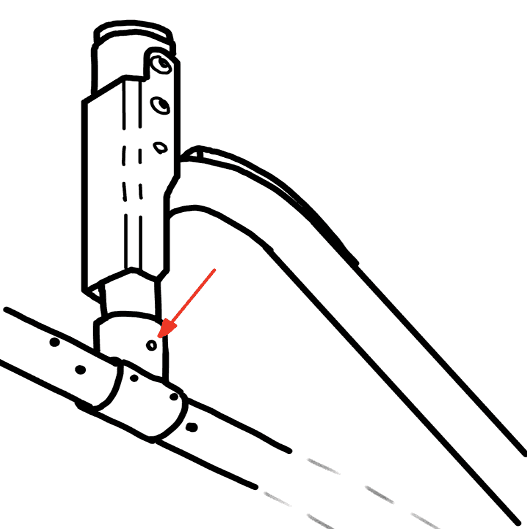
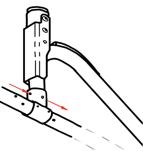
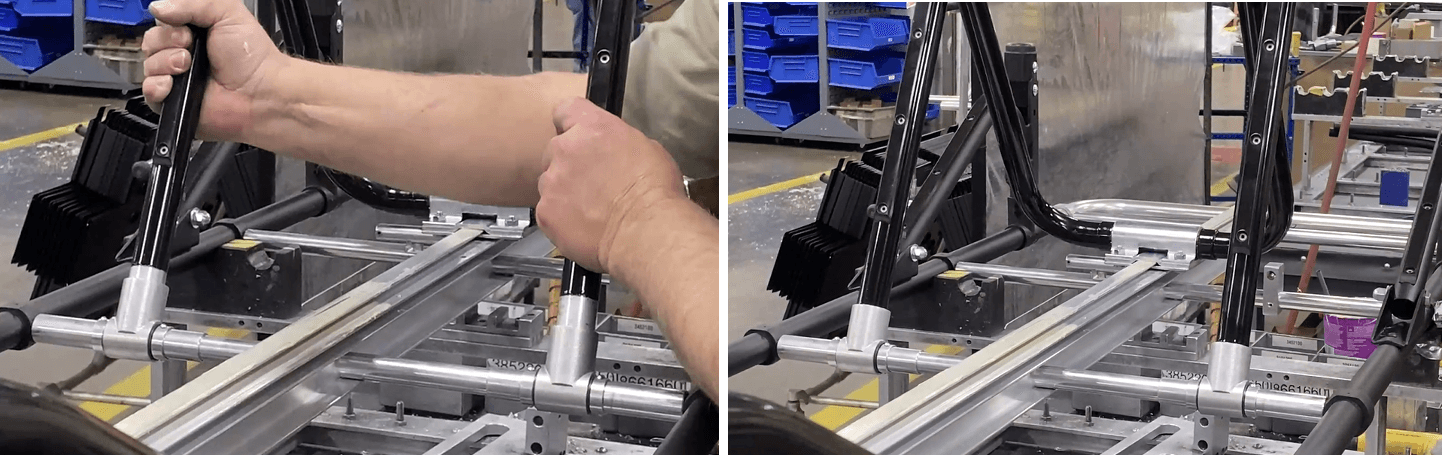
Slide the Operator End Leg Assembly (See “Operator End Leg Subassembly” Work Instructions) onto the I-beam the same way as the Load End Leg Frame (Refer to step 94 and 95).
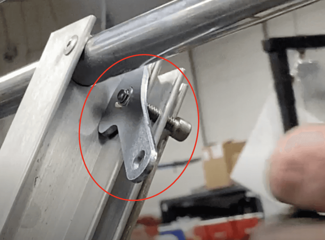
a. Verify the direction of the lock pin weldment, as seen in the picture.

Position the lock pin weldment portion of the operator end leg assembly so that it is by the 2nd crosstube from the operator end.
Move the operator end leg frames (not the brace with the lock pin weldment) so the silver ends of the frames (1525363) go inside the weldment-tees (152-2615).
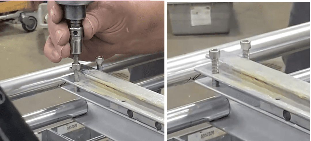
At the four holes between the 2nd and 3rd crosstube from the operator end, next to the operator end lock pin weldment: Insert two 365-1650 (.250-20 X 1.000 Socket Head Cap Screw (SHCS)) and two 3651700 (.250-20 X 1.250 SHCS Zinc Grd 8):
Use a powered socket wrench, 5/32” head, to install the four socket head cap screws.
Place and half-install one 365-1650 (.250-20 X 1.000 SHCS) and one 3651700 (.250-20 X 1.250 SHCS Zinc Grd 8) at the operator end of the I-beam (5/32’ for the powered socket wrench):
Use a marking pin and hammer to mark where to drill on the weldment-tees attached to the operator end legs.
a. Note: mark on the side of the weldment-tee facing upwards (not the side facing the table).
b. Two marks for each weldment-tee, one above the other like so:
Drill with a .152 drill bit through the top marks on each weldment-tee. Drill through all walls. Use drill grease!
Hammer in 3452800 (.156 X 1.375 Roll Pin) into the two holes until the roll pin is flush with the frame.
107. Repeat steps 105 and 106 for the other two drill marks on the weldment-tees. (Drill .152” bit -> Roll pin 345280).
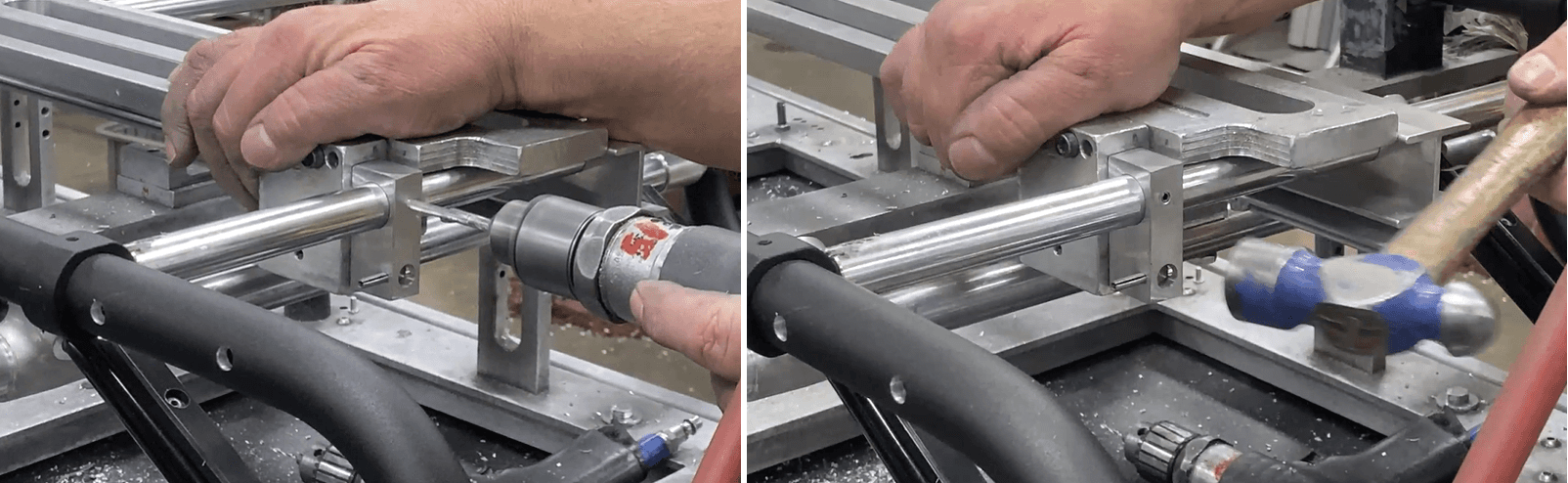
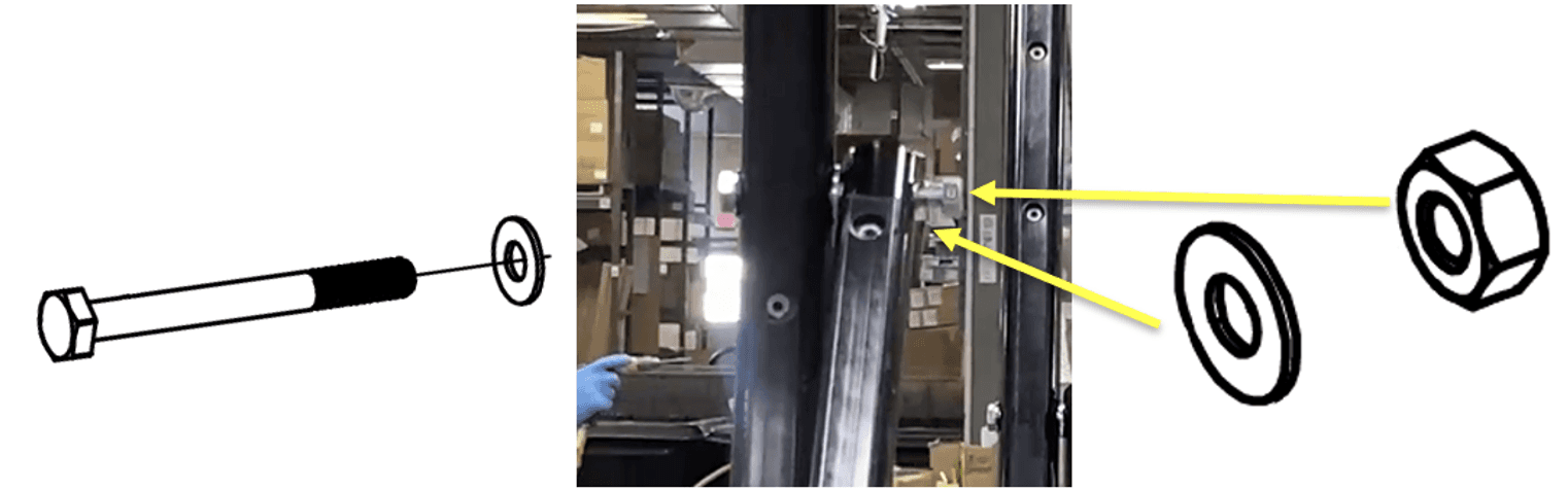
Place 385-6118 (.563X .255X .040 Flat washer) and 8664128 (Bolt sleeve) on a 325-1675 (0.2500-20x2.500 HHCS ZP G5). Make two sets of these!
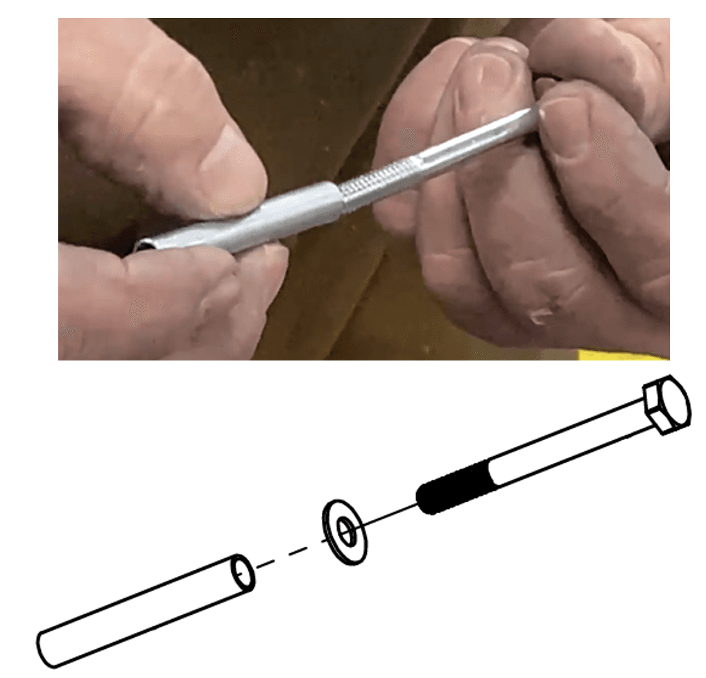
Insert the washer/sleeve/screw combination into the opening on the load end leg frame, the end sticking out and pointing towards the center (the head of the screw should be on the outside of the frame). DON’T push it all the way through the hole.
Place a 385-2500 (.688 X .344 X .063 Flat Washer .313 SAE) on the extruding end of the screw.
Move the same-side load end leg brace and align its hole opening to the extruding screw.
Repeat steps 109 to 111 on the other side; use the second washer/sleeve/screw combination from step 108.
Press the load end leg brace onto the extruding screw so the washer is sandwiched in-between the frame and brace.
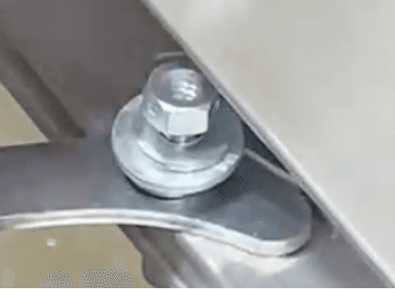
Place a 385-6118 flat washer and a 3302270 (.250-20 Nut Lock Center Hex) onto the extruding screw outside the load end leg brace, as seen below.
Use a power ratchet and a combination wrench on the cap screw and the lock nut to secure them around the frame and brace. (Size .250 for both power ratchet and combination wrench). Do this for BOTH SIDES.
Apply Loctite primer 7649 on the remaining threaded end of the HHCS (both sides).
Apply blue 242 Loctite on the same area (both sides).
Install a 3301700 (.250-20 Acorn Alum Nut) on the remaining threaded end (both sides).
Use two combination wrenches to tighten the acorn nut and HHCS around the load end leg brace and frame.
Slide the operator end and load end subassemblies so the wheel heights are even. Verify the legs are locked in place via the lock pin weldment.
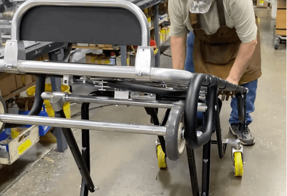
Release the clamps on the fixture via the red levers. Remove the entire assembly from the fixture and place it wheels down on the ground. (video 8343 and 8344)
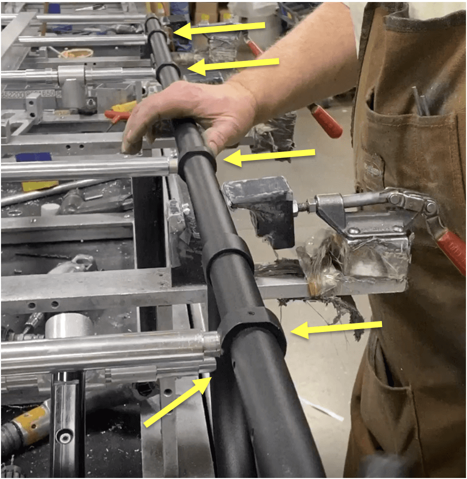
122.) Use the handheld belt sander to sand down any pins sticking out in the areas seen in the pictures below.


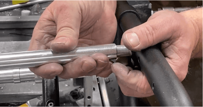
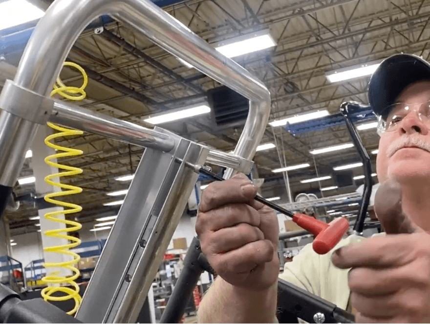
123.) Use a T-wrench to twist in part number 3653944 (.250-20X1.125 SHCS 18-8 SS) or part number 365-1650 (.250-20 X 1.000 SHCS) the end of Detail B on the operators end if needed.
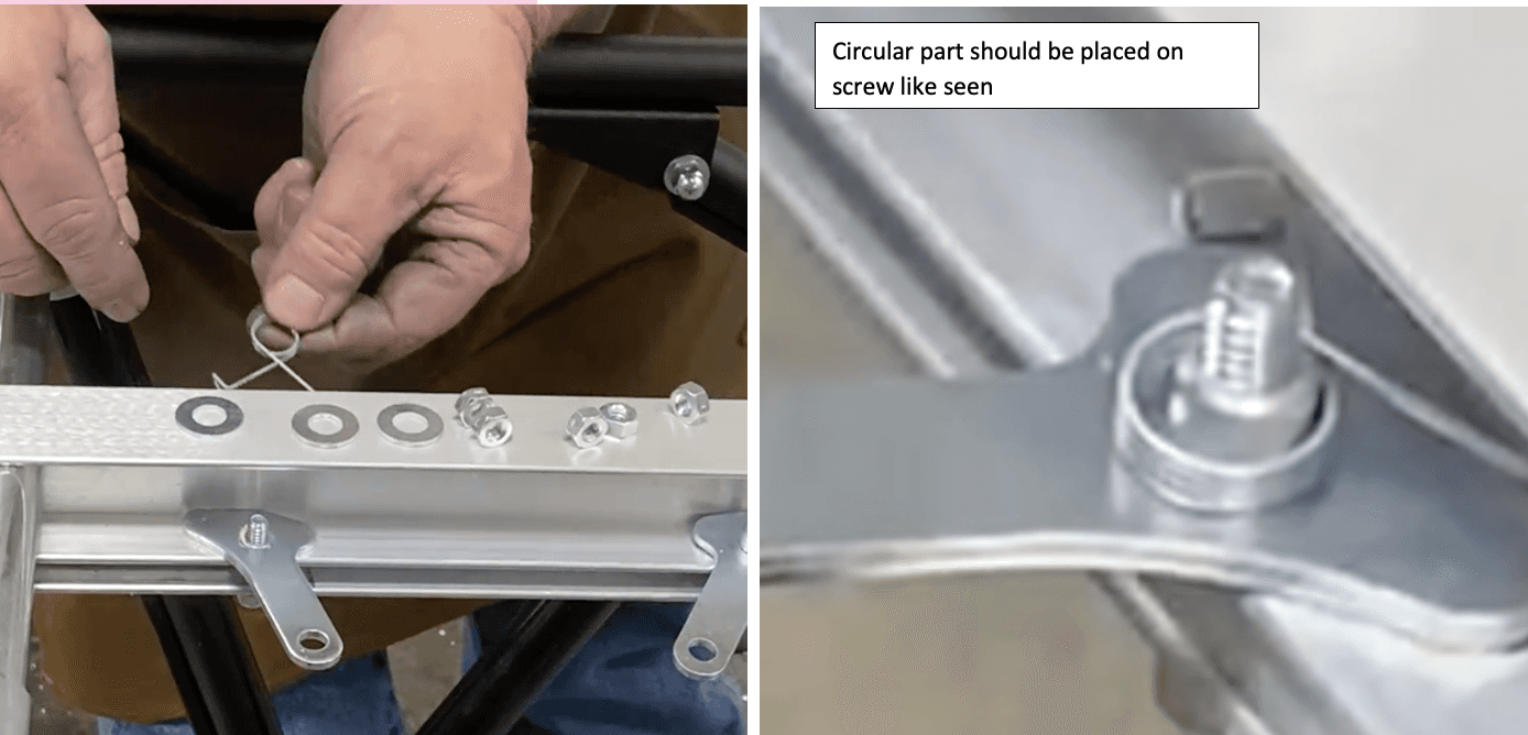
124.) Place part number 3851100 (.563X .328X.010 BOW NP-MD.H) onto both part number 3653944 (.250-20X1.125 SHCS 18-8 SS) and part number 365-1650 (.250-20 X 1.000 SHCS)
125.) Place part number 866-1660 (Bushing) onto both part number 3653944 (.250-20X1.125 SHCS 18-8 SS) and part number 365-1650 (.250-20 X 1.000 SHCS)
126.) Place part number 863-4210 (Linkage, Limited Release) onto where part number 866-1660 (Bushing) was just placed on part number 365-1650 (.250-20 X 1.000 SHCS).
127.) Place another part number 3851100 (.563X .328X.010 BOW NP-MD.H) onto where part number 863-4210 (Linkage, Limited Release) was just placed.
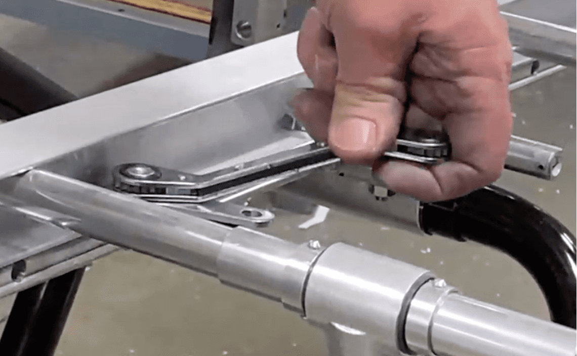
128.) Using a wrench and a T-handle wrench to tighten on part number 3302270 (.250-20 Nut Lock Center Hex) where you just placed another part number 3851100 (.563X .328X.010 BOW NP-MD.H)
129.) Repeat steps 126-128 for part number 3653944 (.250-20X1.125 SHCS 18-8 SS) on the other side
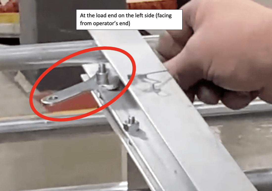
130.) Place part number 866-1660 (Bushing) onto the shorter screw sticking out towards the middle of the left side (facing from operator’s end) of Detail B.
131.) Place one part number 866-0850 (.375X.058 Spacer) onto the longer screw sticking out next to where part number 866-1660 (Bushing) was just placed. Place two more of the same part on the longer screws on the other side.
132.) Place another part number 866-0850 (.375X.058 Spacer) onto the longer screw sticking out at the end towards the Load end of the same side.
133.) Place five of part number 863-4210 (Linkage, Limited Release) onto all the spots shown below on Detail B, ensuring to grease the bottom of the thicker end before doing so.
134.) Place part number 269-0117 (Spring- Reverse Trigger) onto part number 863-4210 (Linkage, Limited Release) on the right side (facing from operator’s end) where seen in the picture below.
135.) Place part number 3854300 (.375X.813X.063 FW ST TCZ) on top of where part number 269-0117 (Spring-Trigger) was just placed.
136.) Place part number 385-2400 (.625X .281X.063 FLAT .250 SAE) on top of where part number 3854300 (.375X.813X.063 FW ST TCZ) was just placed.
137.) Place part number 3302270 (.250-20 Nut Lock Center Hex) on top of where part number 385-2400 (.625X .281X.063 FLAT .250 SAE) was just placed.
138.) Using a part number 269-0116 (Spring-Trigger) instead, repeat steps 134-137 but on the left side (facing from operator’s end) where shown below.
139.) Where seen below, place another part number 269-0117 (Spring- Reverse Trigger) and repeat steps 134-137 again.
140.) Place two of part number 3302270 (.250-20 Nut Lock Center Hex) on top of part number 385-2400 (.625X .281X.063 FLAT .250 SAE) in the locations seen below.
141.) Tighten all of the part number 3302270 (.250-20 Nut Lock Center Hex) where there were no Spring Triggers placed
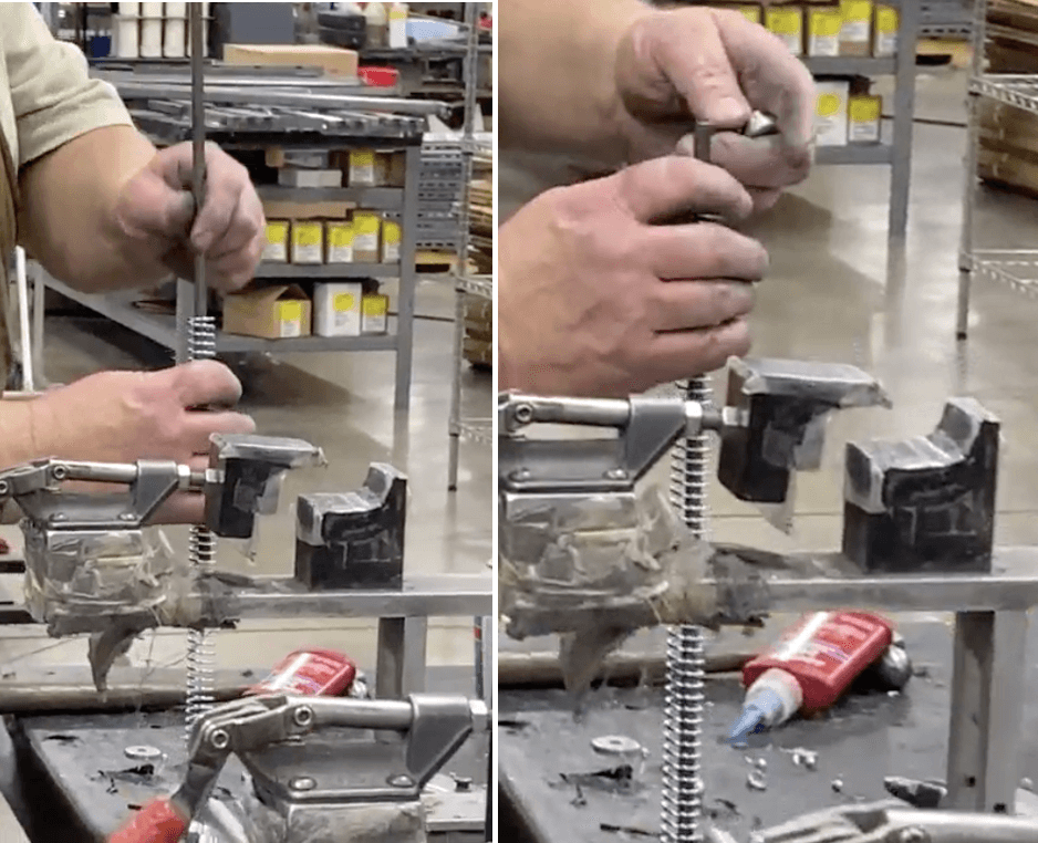
142.) Take part number 8602620 (Spring Rod, Long) and feed it through part number 2688500 (Spring, Leg Return)
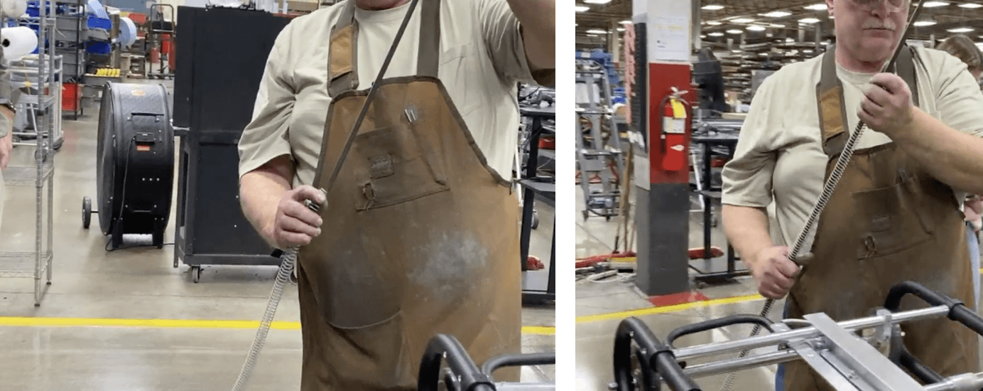
143.) Insert one end of the combined part into the hole on part number 8093620 (Hanger, Spring Rod) on the operator’s end and insert the other end into the hole on part number 8122700 (Pusher, Spring)
144.) Take part number 8602630 (Spring Rod, Short) and feed it through part number 2689905 (Spring, Return)
145.) Take part number 8122710 (Bushing, Spring Guide) and feed it down part number 8602630 (Spring Rod, Short) until it hits part number 2689905 (Spring, Return).
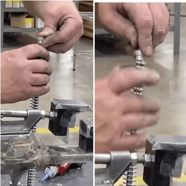
146.) Repeat step 145 on the other side.
147.) Insert one end of the combined part into the hole on part number 8093620 (Hanger, Spring Rod) on the load end and insert the other end into the hole on the other side of part number 8122700 (Pusher, Spring)
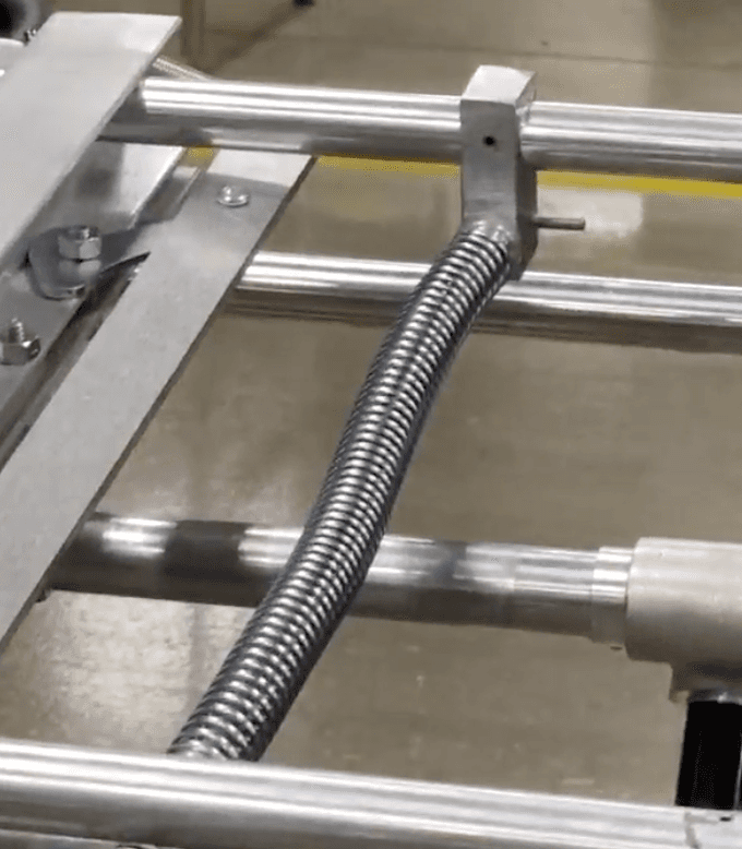
148.) Use a roll pin starter to hammer in part number 3451700 (.156 X .625 Roll Pin) into the side of part number 8093620 (Hanger, Spring Rod) on the load end.
149.) Bunch up part number 2688500 (Spring, Return) and apply grease to part number 8602630 (Spring Rod, Short).
150.) Bunch up part number 2688500 (Spring, Leg Return) and apply grease to part number part number 8602620 (Spring Rod, Long).
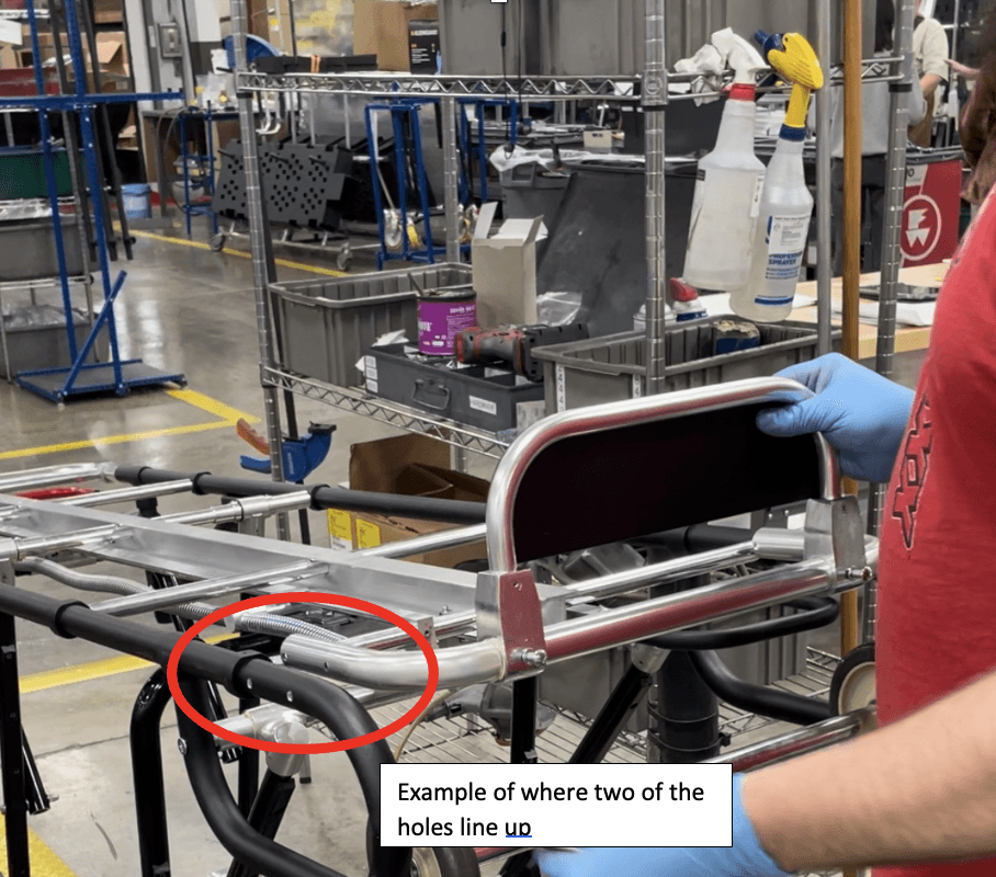
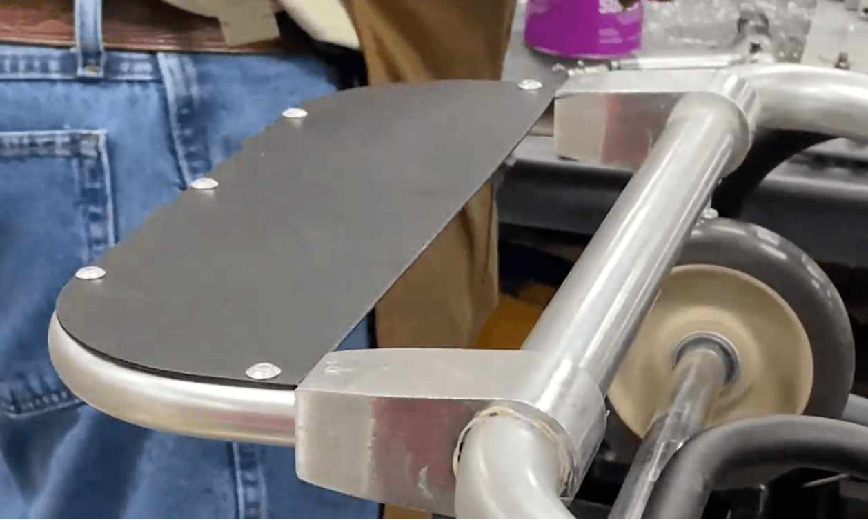
152.) Grab the pre-assembled footrest and line the two holes on the sides of part number 1525989 (Frame, Load End, Minimaxx) up with the two holes on the load end of both part number 1525356 (Frame, Main Half Left) and part number 1525355 (Frame, Main Half Right).
153.) Place four of part number 3161604 (.250-20X2 500 Carriage Bolt SS) all the way through the four holes on both parts on each side.
154.) Hammer in each of the four of part number 3161604 (.250-20X2 500 Carriage Bolt SS)
155.) Place 2 of part number 3302270 (.250-20 Nut, Lock Center Hex) onto the ends of the part number part number 3161604 (.250-20X2 500 Carriage Bolt SS) that you just hammered through on the right side (facing from operator’s end)
156.) Repeat step 155 for the left side.
157.) Loosen the two of part number 335-2338 (.250 – 20 X .875 PHMS PHIL) on the back of the footrest assembly.

158.) Flip the footrest assembly down so that it is lying flat.
159.) Use a power wrench to tighten each of the four of part number 3302270 (.250-20 Nut, Lock Center Hex) you just placed.
160.) Spray Loctite Primer (690-4579) on all four threads where you just tightened part number 3302270 (.250-20 Nut, Lock Center Hex).
161.) Apply Blue Removable Threadlocker to the four threads where you just sprayed.
162.) Place four of part number 3301700 (.250-20 Nut, Acorn Alum) onto all four places where the Blue Removable Threadlocker was just placed.
163.) Tighten all four of part number 3301700 (.250-20 Nut, Acorn Alum) that were just placed using a wrench.
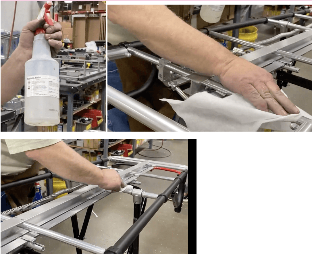
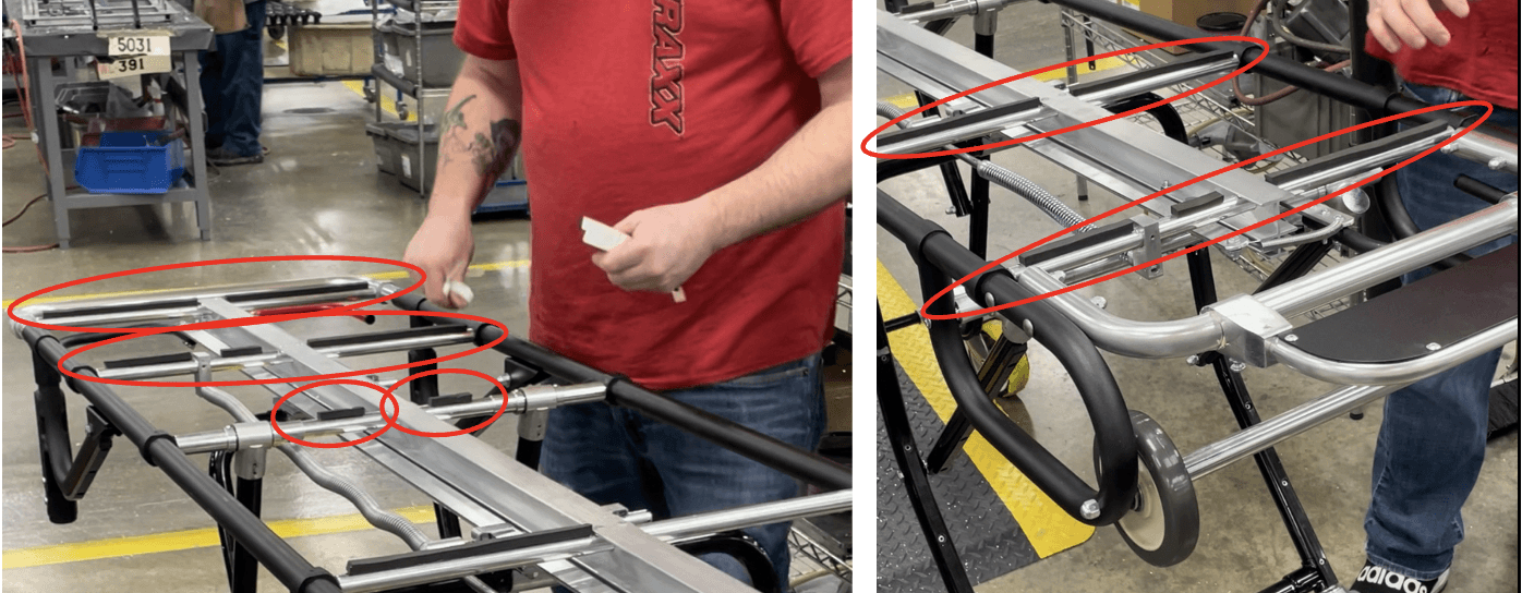
164.) Using alcohol, wipe down all 5 of part number 8125078 (X-Tube Stiffener – 24 Minimaxx), which are the center bars.
165.) Place the correct Styrofoam sticker in all the places circled below.
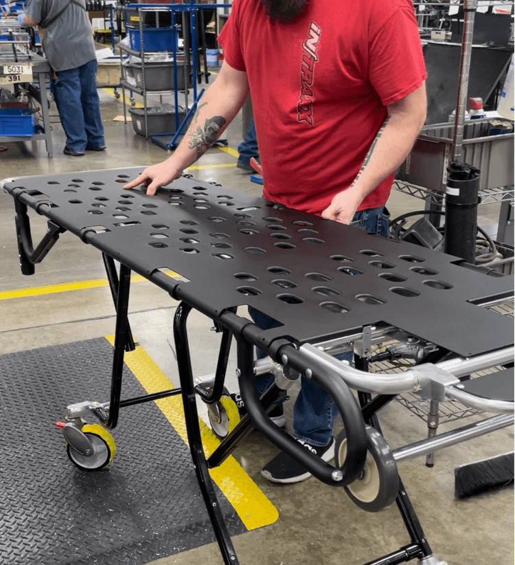
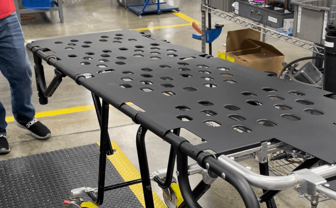
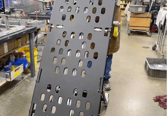
166.) Place part number 8159615 (Panel, Body) onto the Frame Assembly (Detail A) like seen in the picture below.
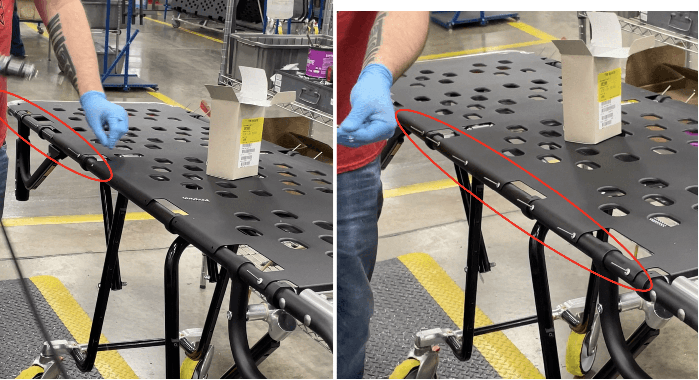
167.) Staring at the load end, use drill bit .149 to drill two holes through the hole templates on part number 8159615 (Panel, Body) through one wall of the Frame Assembly (Detail A).
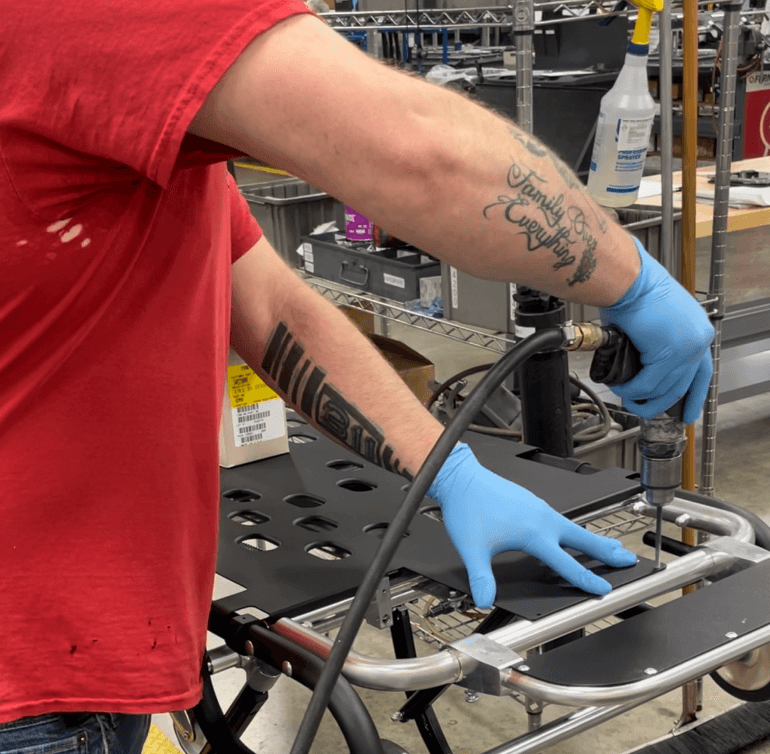
168.) Place two of part number 340-2200 (AD- 66-H Rivet, Pop) into the holes that were just drilled.
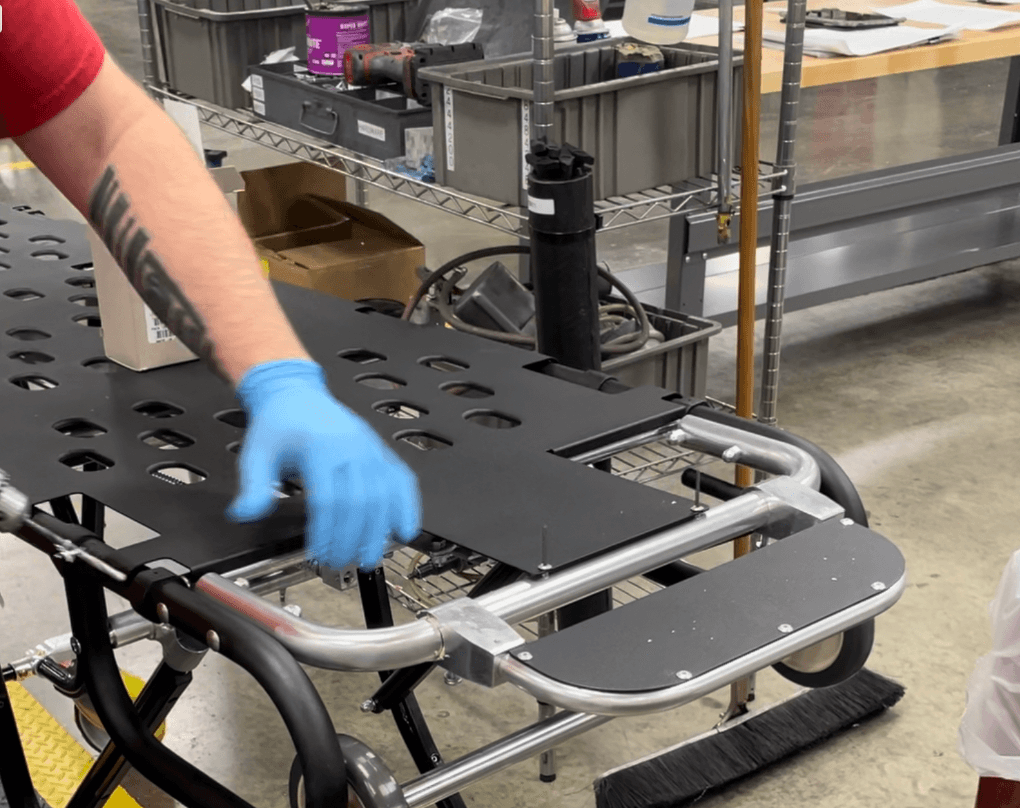
169.) Repeat steps 167-168 but for both sides, there should be 24 holes drilled and 24 of part number 340-2200 (AD- 66-H Rivet, Pop) placed.
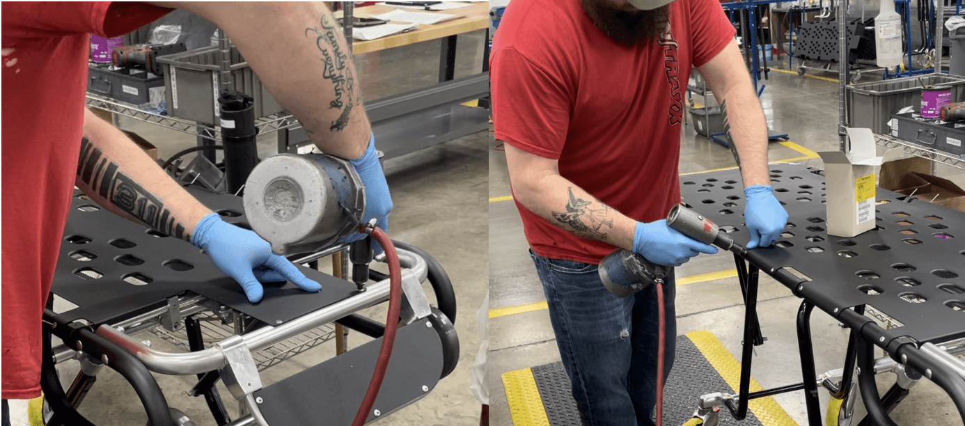
170.) Use a Rivet Gun to set all 26 of part number 340-2200 (AD- 66-H Rivet, Pop).
171.) Flip footrest back up and slightly tighten both of part number 335-2338 (.250 – 20X .875 PHMS PHIL) that are on the back.
172.) Test to make sure the 24-MiniMAXX is fully functional.
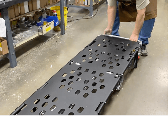
173.) Wipe down the surface and place the Ferno label sticker in designated place.
